
User`s guide


Connecting GPIO • 35
Version 1.2 July 2010
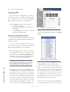
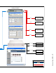
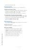
status indicators change as we turn the channel on
and off, as shown in Figure B-3.
Figure B-3: Pin status indicators showing
GPIO port activity
See how easy that was? Simply assigning an existing
audio source to a GPIO port automagically config-
ures the port for the type of device supplying the au-
dio, and send the appropriate logic commands to that
port when the source is assigned to a Element chan-
nel.
GPIO Snake
When you “connect” two GPIO ports together via
their port configuration, we call that a GPIO snake. This
may be useful to make GPIO logic travel over the net-
work from one room to another. You might have a News-
room with some 2-way radio PTT switches but the radios
are in your engineering rack room. GPI of a node in the
Newsroom could be translated to GPO of a node at the
location of the radios. The GPI of each port is translated
to GPO of the other corresponding port. To accomplish
this GPIO mapping (or snake), you will simply specify
the IP Address and Port of the two GPIO’s that you wish
to “connect”.
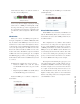
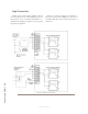
To illustrate the example above, let’s say we have:
• Newsroom GPIO node with IP address
192.168.10.101 and we wish to use port 3 on this
node.
• Engineering Room GPIO node with IP address
192.168.10.102 using port 2 on that node.
Newsroom GPIO port 3 would be configured as
shown below:
The Engineering Room GPIO port 2 would look
something like this:
Virtual GPIO Connections
Virtual GPIO is used extensively with IP-Intercom
stations. This flexibility allows you to easily associate an
external intercom source with a GPIO port that may be
in a different studio.
This configuration is very similar to that described
above however one of the ports is not a physical port. In
the case of an IC.20 IP-Intercom unit, there is one physi-
cal GPIO port that may be used in the same manner as a
GPIO port on any other GPIO node. The IC.20 also has
several virtual ports that exist in the software. If we wish
to “connect: these virtual ports to physical port, we must
specify a connection in the same manner as we did when
we created a GPIO snake in the previous example.
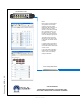
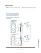
The diagram on the following two pages gives you a
real world example of how you will configure and con-
nect IP-Intercom GPIO to non-Livewire external equip-
ment. The example we have used is the interconnection
of a couple of external analog intercom sources to an
Axia IC.20 IP-Intercom unit. These external sources
might be existing analog studios or other workstations
that have only analog audio sources and physical switch-
es for Talk/Listen control.