
User`s guide


Connecting GPIO • 39
Version 1.2 July 2010
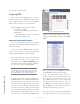
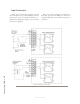
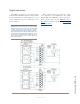
Output Connections
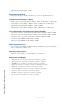
The GPIO port’s outputs are opto-isolated. Current
should be limited 100 mA through each output, with the
total current draw from the +5 Volt supply not to exceed
3 amps. Figure B-5 shows the recommended connec-
tions for outputs:
Note: Some external devices will allow a logic
control input “sink to ground” to activate. Thus,
some devices may not work with an Axia GPO
control, because they may not fully achieve
ground through the output transistor. The volt-
age drop between the collector and emitter may
not be low enough to activate the device, so an
external relay controlled by the GPO may need
to be used to provide a “dry” contact closure to
the external device.
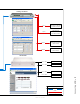
Please note that this section is provided as a “jump-
start” introduction to Axia GPIO nodes. For a fuller
understanding of the GPIO node’s options and require-
ments, you may wish to read the GPIO Node User’s
Manual that is available for download at www.AxiaAu-
dio.com/downloads/ .
Figure B-5: GPIO output connections