EoC 1-01 Ethernet over Coax Operation Instructions
Operation Instructions | EoC 1-01 | Ethernet over Coax Contents 1. Product description ....................................................................................................................................... 4 1.1. Disposal of wastes ................................................................................................................................ 4 1.2. Scope of delivery............................................................................................................
Safety instructions Do NOT use the device near water or in rooms with high humidity such as humid cellars or near swimming pools. Do NOT use the device outdoors. All connections must be located inside a building. Keep the device away from moisture, dust or corrosive liquids. Do NOT install the device, use it or perform maintenance during a thunderstorm. There is a risk of electric shock during thunderstorm. Connect ONLY appropriate accessories to the device.
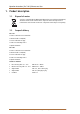
Operation Instructions | EoC 1-01 | Ethernet over Coax 1. Product description 1.1. Disposal of wastes Your device is marked with the WEEE symbol (Waste Electronics and Electrical Equipment). This means that the electrical and electronic components must not be disposed of as residual waste. Used electrical and electronic components must be disposed of separately. 1.2. Scope of delivery EoC 1-01 1 x EoC 1-01 Ethernet over Coax Modem 1 x Network cable 1.
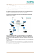
1.3. Field of application The EoC 1-01 modem allows feeding in of IP data signals from the Internet, for example via a router in an existing coaxial antenna distributor, such as SAT-IF-, DVB-T, CATV- or head end distribution systems (in the star or tree distribution). Several Eoc 1-01 modems communicates in a Peer-to-Peer mode. This means that each modem can communicate with each modem in the network. The advantage of an ethernet solution over a coax solution is that no new network cables must be laid.
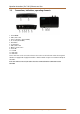
Operation Instructions | EoC 1-01 | Ethernet over Coax 1.4. Connections, indications, operating elements 1. Power ON/OFF 2. LAN 2, RJ 45 socket 3. EoC F-socket (data + TV 2-862 MHz) 4. TV- F socket (85-862 MHz) 5. Reset button 6. Security button 7. LAN 1, RJ 45 socket 8. Mains socket 110-230 V 9. Power LED 10. EoC LED 11. LAN 1 LED 12. LAN 2 LED A TV or radio device can be connected to the TV-F socket on the rear side of the EoC modem.
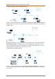
1.5. Application examples All components in the distribution structure must support the return channel frequency range 2-68 MHz. This also applies to SAT multiswitches, the passive distribution components and for antenna sockets. Feeding in of IP data in a SAT-IF distribution structure: If the terrestrial input of the SAT multiswitch is not assigned, it must be terminated with a 75 Ohm terminating resistor. Example 1: The feeding of the IP signal is performed via the return channel capable antenna socket.
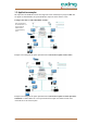
Operation Instructions | EoC 1-01 | Ethernet over Coax Feeding in of IP data in a CATV distribution structure: Example 3: The feeding of the IP signal is performed via the return channel capable antenna socket. If the IP-data are fed via the antenna socket, a high-pass filter TZU 19-65 must be installed in the coaxial supply line (amplifier output). Example 4: IP data feeding for exactly one antenna socket: The feeding of the IP signal is performed via the EoC combiner TZU 40-03.
2. Installation and commissioning 1. Connect the router with the enclosed Ethernet cable to one of both RJ-45 LAN sockets of the EoC modem. 2. Connect the EoC socket to the available antenna network structure (see example 1 to 4). There are several ways to feed the IP data into the existing antenna network structure.
Operation Instructions | EoC 1-01 | Ethernet over Coax 3. Basic functions After having switched on the EoC modem, the LEDs should indicate the following states: The green Power LED is lit. – After approx. 10 seconds, the LEDs are lit/flashing as follows: – EoC LED green (flashes in case of data traffic) – LAN LED green (flashes in case of data traffic) – WiFi LED green (if WiFi is switched on) green (flashing in case of data traffic) 3.1.
4. EoC network with encryption An EoC network consists of two or several (maximum 64) EoC modems which use the same network key. In an existing antenna system with several participants, all devices can communicate with each other. Therefore, you should create a private EoC network. Securing your EoC network allows you to protect the information sent via the network from unauthorized access. This is particularly important in multi-family homes, office buildings, schools and other buildings.
Operation Instructions | EoC 1-01 | Ethernet over Coax 5. Troubleshooting 5.1. LEDs LEDs The LEDs indicate an "activity" and are used for troubleshooting. Power LED off Make sure that the network cable is connected correctly. Make sure that the mains switch of the EoC modem is switched on. LAN LED is not flashing No data traffic.
6. Technical data 6.1. Data sheet Frequency range EoC input/output 2…1006 MHz IP signal 2…68 MHz TV output 85…1006 MHz Through loss <0,5 dB Output level min. 1…30 MHz 100 dBμV Output level min.
Operation Instructions | EoC 1-01 | Ethernet over Coax 6.2.
2015-01-01 | © AXING AG Schweiz | Konstrukions -, Typenänderung, Irrtümer und Druckfehler vorbehalten 15
Operation Instructions | EoC 1-01 | Ethernet over Coax 16 2015-01-01 | © AXING AG Schweiz | Konstrukions -, Typenänderung, Irrtümer und Druckfehler vorbehalten