EoC 2-01 Ethernet over Coax | WiFi Operation Instructions
Operation Instructions | EoC 2-01 | Ethernet over Coax | WiFi Contents 1. Product description ....................................................................................................................................... 4 1.1. Disposal of wastes ................................................................................................................................ 4 1.2. Scope of delivery.....................................................................................................
Safety instructions Do NOT use the device near water or in rooms with high humidity such as humid cellars or near swimming pools. Do NOT use the device outdoors. All connections must be located inside a building. Keep the device away from moisture, dust or corrosive liquids. Do NOT install the device, use it or perform maintenance during a thunderstorm. There is a risk of electric shock during thunderstorm. Connect ONLY appropriate accessories to the device.
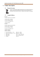
Operation Instructions | EoC 2-01 | Ethernet over Coax | WiFi 1. Product description 1.1. Disposal of wastes Your device is marked with the WEEE symbol (Waste Electronics and Electrical Equipment). This means that the electrical and electronic components must not be disposed of as residual waste. Used electrical and electronic components must be disposed of separately. 1.2. Scope of delivery EoC 2-01 1 x EoC 2-01 Ethernet over Coax Modem 1 x Network cable 1.
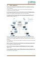
1.3. Field of application The EoC 2-01 modem allows feeding in of IP data signals from the Internet, for example via a router in an existing coaxial antenna distributor, such as SAT-IF-, DVB-T, CATV- or head end distribution systems (in the star or tree distribution). Several Eoc 2-01 modems communicates in a Peer-to-Peer mode. This means that each modem can communicate with each modem in the network. The advantage of an ethernet solution over a coax solution is that no new network cables must be laid.
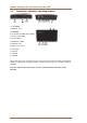
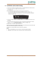
Operation Instructions | EoC 2-01 | Ethernet over Coax | WiFi 1.4. Connections, indications, operating elements 1 2 3 4 5 6 7 8 9 1. Power ON/OFF 2. LAN, RJ 45 socket 3. WiFi ON/OFF 4. EoC F socket 2-862 MHz (data 2-65 MHz) 5. TV F socket 85-862 MHz 6. EoC Reset button 7. WiFi WPS/Reset button 8. LAN, RJ 45 socket 10 11 12 13 9. Mains socket 110-230 V 10. Power LED 11. EoC LED 12. LAN LED 13. WiFi LED A TV or radio device can be connected to the TV-F socket on the rear side of the EoC modem.
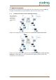
1.5. Application examples All components in the distribution structure must support the return channel frequency range 2-68 MHz. This also applies to SAT multiswitches, the passive distribution components and for antenna sockets. 1.5.1. Feeding in of IP data in a SAT-IF distribution structure: If the terrestrial input of the SAT multiswitch is not assigned, it must be terminated with a 75 Ohm terminating resistor.
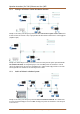
Operation Instructions | EoC 2-01 | Ethernet over Coax | WiFi 1.5.2. Feeding in of IP data in a CATV distribution structure: Example 3: The feeding of the IP signal is performed via the return channel capable antenna socket. If the IP-data are fed via the antenna socket, a high-pass filter TZU 19-65 must be installed in the coaxial supply line (amplifier output). Example 4: IP data feeding for exactly one antenna socket: The feeding of the IP signal is performed via the EoC combiner TZU 40-03.
2. Installation and commissioning 1. Connect the router with the enclosed Ethernet cable to one of both RJ-45 LAN sockets of the EoC modem. 1. Connect the EoC socket to the available antenna network structure (see example 1 to 4). There are several ways to feed the IP data into the existing antenna network structure.
Operation Instructions | EoC 2-01 | Ethernet over Coax | WiFi 3. Basic functions After having switched on the EoC modem, the LEDs should indicate the following states: The green Power LED is lit. – After approx. 10 seconds, the LEDs are lit/flashing as follows: – EoC LED green (flashes in case of data traffic) – LAN LED green (flashes in case of data traffic) – WiFi LED green (if WiFi is switched on) green (flashing in case of data traffic) 3.1.
4. EoC network with encryption An EoC network consists of two or several (maximum 64) EoC modems which use the same network key. In an existing antenna system with several participants, all devices can communicate with each other. Therefore, you should create a private EoC network. Securing your EoC network allows you to protect the information sent via the network from unauthorized access. This is particularly important in multi-family homes, office buildings, schools and other buildings.
Operation Instructions | EoC 2-01 | Ethernet over Coax | WiFi 5. Settings for the WiFi network The EoC 2-01 WiFi modem is configured using a web browser. The factory IP address is 192.168.100.111 and the subnet mask is 255.255.255.0. The WiFi WPS/Reset button is used to reset the WiFi router to the factory IP address 192.168.100.111. Press the WiFi WPS/Reset button and keep it pressed for at least 10 seconds. Then switch off the device and switch it on again. The device is now in the delivery state again.
5.2. Operation Mode The main page, called "Setup Wizard" offers you the most basic settings needed for Wi-Fi operating mode. After selecting one of the following options, you will be guided through the installation process. You are able to choose one of the following functions: Bridge AP In this mode the device acts as a single access point. The network the device is attached to is being extended via the LAN ports (device acts as switch) and via the Wi-Fi interface.
Operation Instructions | EoC 2-01 | Ethernet over Coax | WiFi 5.3. Wireless Settings 5.3.1. Wireless Basic Settings On this page the settings for the local Wi-Fi Access Point are set. Attention: Only 2.4 GHz-Mode is supported! In the "Mode" menu you can select whether you want the device to act as "AP" (Access Point), "Client" (of another Wi-Fi-Network) or "AP + WDS". 5.3.2. Wireless Security Setup On this page the settings for Wireless Security are set.
5.3.3. Wireless Site Survey Before applying the settings you have to decide to which Wi-Fi network you want the EoC 2-01 to connect to. You can rescan the available networks using the "Site Survey" button on top. 5.3.4. Wireless Advanced Settings Very specific advanced Wi-Fi settings can be set here. For example you can adjust the RF Output Power, which directly correlates with the Wi-Fi coverage range.
Operation Instructions | EoC 2-01 | Ethernet over Coax | WiFi 5.3.5. Wireless Schedule The Wireless Schedule allows the user to set times at which the Wi-Fi broadcast is being deactivated. You can for instance choose to disable Wi-Fi at night. This feature is disabled by default. 5.4. TCP/IP Settings 5.4.1. LAN Interface Setup On this page the IP Address and Subnet Mask of the local EoC 2-01 device is being set.
5.5. Management 5.5.1. Access Point Status The status page shows some basically information about the system, Wi-Fi Connection and LAN Connection. 5.5.2. Statistics This page gives you an overview about sent / received packets inside the specific networks.
Operation Instructions | EoC 2-01 | Ethernet over Coax | WiFi 5.5.3. Time Zone Setting Time, Date and Time-zone can be adjusted here. Optionally a NTP (Network Time Protocol) Server can be added here, too. 5.5.4. System Log On this page you can view the current system log. Also you can specify a log server to upload the logs to.
5.5.5. Upgrade Firmware This page enables you to upload new released firmware versions. In case of an update you receive a document with additional information about how to update the device. In some cases it is necessary to clear your browser-cache after you upgraded your firmware. Updates are published on our website: http://www.axing.com/. 5.5.6. Save / Reload Settings At this page you can export the current configuration into a file to download onto your local computer.
Operation Instructions | EoC 2-01 | Ethernet over Coax | WiFi 5.5.7. Password Setup This page allows you to customize the used password for accessing the web-front-end.
6. Troubleshooting 6.1. LEDs The LEDs indicate an "activity" and are used for troubleshooting. Power LED off Make sure that the network cable is connected correctly. Make sure that the mains switch of the EoC modem is switched on. LAN LED is not flashing No data traffic.
Operation Instructions | EoC 2-01 | Ethernet over Coax | WiFi 7. Technical data 7.1. Data sheet Frequency range EoC input/output 2…1006 MHz IP signal 2…68 MHz TV output 85…1006 MHz Through loss <0,5 dB Output level min. 1…30 MHz 100 dBμV Output level min.
7.2.
Operation Instructions | EoC 2-01 | Ethernet over Coax | WiFi 24 2015-01-1916 | © AXING AG Schweiz | Konstrukions -, Typenänderung, Irrtümer und Druckfehler vorbehalten