
User's Manual

Stealth Reader
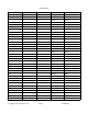
3 Wire Green Green
Black Black
Sensus SR II Encoded Red Red
2 Wire Green Red
Black Black
Invensys AMR System Encoded Red Red
Green Green
Black Black
Neptune E-coder Encoded Red Black
Green Red
Black Green
Badger Absolute Encoder Encoded Red Red
Green Green
Black Black
Metron Spectrum 22 Encoded Red Red
Green Green
Black Black
AMCO InVision Encoded Red Green
White Red
Black Black
Invensys/Sensus ICE Encoded Red Red
Green Green
Black Black
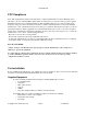
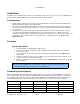
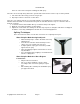
When connecting the Stealth Reader to the Register there are screws or wires connected to the Register. The
screws will be labeled with either the word or the starting letter of the colors. So there maybe a “R, G, B, etc.”
next to there own nob. This is done so that the wiring can be done properly, and get the wires connected to the
right color.
When actually connecting the Stealth Reader to the Register please follow the
following procedure.
1. Check the Chart above to see what wires need to be connected
together based on the Brand and Model of the Register.
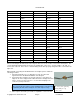
2. Connect the wires using the UY gel cap connectors. If the wires are
stripped, cut off the stripped ends. Wires must have unstripped ends in
order to use the gel cap connectors. Use the Klein Crimping tool to
secure the gel cap connectors.
3. Pulse registers don't have pre-install test capabilities. So be sure the
Copyright 2013, Axiometric, LLC Page 8 Confidential
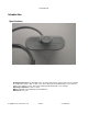
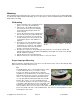
A correct wire splicing
useing UY gel cap
connectors.
Note:
Once connected to the register, test the Stealth Reader connections by
programming the unit and receiving the encoded setup message.