GOT815-834 15” XGA TFT Touch Panel Computer User’s Manual IP69K certification distinguishes the highest level of reliability
Disclaimers This manual has been carefully checked and believed to contain accurate information. Axiomtek Co., Ltd. assumes no responsibility for any infringements of patents or any third party’s rights, and any liability arising from such use. Axiomtek does not warrant or assume any legal liability or responsibility for the accuracy, completeness or usefulness of any information in this document. Axiomtek does not make any commitment to update the information in this manual.
Safety Precautions Before getting started, please read the following important safety precautions. 1. The GOT815-834 does not come equipped with an operating system. An operating system must be loaded first before installing any software into the computer. 2. Be sure to ground yourself to prevent static charge when installing the internal components. Use a grounding wrist strap and place all electronic components in any static-shielded devices.
Table of Contents Disclaimers...................................................................................................... i Disclaimers..................................................................................................... ii Safety Precautions........................................................................................ iii CHAPTER 1 Introduction ............................................................ 1 1.1 1.2 1.2.1 1.2.2 1.2.3 1.3 1.4 1.5 General Description ....
GOT815-834 User’s Manual CHAPTER 1 Introduction This chapter contains general information and detail ed specifications of the GOT815834. Chapter 1 includes the following sections: General Description Specification Dimensions I/O Outlets Package List 1.1 General Description The GOT815-834 is a fan-less and compact-size touch panel computer, equipped TM with a 15” XGA TFT LCD display and low power consumption Intel ○R Atom E3827 ® ® 1.75GHz processor.
GOT815-834 User’s Manual 1.2 Specifications 1.2.1 Main CPU Board CPU Intel® Atom TM E3827 1.75GHz processor onboard System Memory One 204-pin DDR3L(1.35V) SO-DIMM socket Maximum memory up to 8GB BIOS America Megatrends BIOS 1.2.2 I/O System Standard I/O 2 x RS-232/422/485(default RS-232) 4 x USB 2.
GOT815-834 User’s Manual 1.2.3 System Specification 12.1” TFT LCD 15” XGA 420nits Heat Dispensing Design Disk drive housing Net Weight -20℃ to 55℃ Relative Humidity 382mm x 305mm x 55mm Operation Temperature 5.2Kgs (11.46 lb) Dimension (Main Body Size) One 2.5” SATA drive (optional) 10% to 90% @ 40℃, Non-Condensing Vibration 5 to 500 Hz, 2.0 G for CFast or mSATA 5 to 500 Hz, 2.0 G for SSD 1.
GOT815-834 User’s Manual 1.3 Dimensions This diagram shows you dimensions and outlines of the GOT815-834.
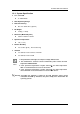
GOT815-834 User’s Manual 1.4 I/O Outlets Please refer to the following illustration for I/O locations of the GOT815-834. 1 4 2 5 6 7 8 9 3 No Introduction Function 1 Backlight ON/OFF 2 Brightness Adjust 3 Power Switch(ATX) 4 DC power connector 5 COM1(configure RS422/485, default RS-232) 6 COM2(configure RS422/485, default RS-232) 7 Ethernet 8 USB2.0 × 2 9 USB2.
GOT815-834 User’s Manual 1.5 Package List W hen you receive the GOT815-834, the bundled package should contain the following items: GOT815-834 x 1 Driver CD x1 DC cable x1 Power Adapter (optional) Water-proof Power / USB / LAN / RS-232 cables (optional) VESA ARM(optional) If you can not find the package or any items are missing, please contact Axiomtek distributors immediately.
GOT815-834 User’s Manual CHAPTER 2 System Configurations The GOT815-834 provides rich I/O ports and flexible expansions for you to meet different demand, for example, CF. The chapter will show you how to install the hardware. It includes: I/O Pin Assignment Hard Disk and DRAM Wireless LAN Card (Optional) Water-proof cables (Optional) Hanging and VESA mounting (Optional) 2.
GOT815-834 User’s Manual 2.1.2 Ethernet The GOT815-834 is equipped with a high performance Plug and Play Ethernet interface, full compliant with IEEE 802.3 standard , and can be connected with a M12 LAN connector. Please refer to detailed pin assignment list below: Pin Signal Pin Signal L1 MDI0P L5 MDI2P L2 MDI0N L6 MDI2N L3 MDI1P L7 MDI3P L4 MDI1N L8 MDI3N 2.1.3 USB Port The USB is a Universal Serial Bus (compliant with USB 2.0 (480Mbps)) connector on the rear I/O.
GOT815-834 User’s Manual 2.2 Water-proof Cables GOT-800 series uses specific M12 connector for water-proof. order each cable base on application. Therefore you will There are four kind cables of GOT815, by the optional, if you will apply the USB, COM or Etherent then you can select a cable for the package . The Power cable included in the accessory box, when you will need the power adapter, also it can be sesected by optional. 2.2.1 Power cable Please follow pin assignement for the power input.
GOT815-834 User’s Manual 2.2.2 Power adapter for GOT815-834 If you order the power adapter, you should choose the power cord ty pe for your location. The power adapter is +24VDC(70W ), 110-240V which is combined M12 connector. 2.2.3 COM There are two COM cables which are combined M12 connector. Also, you can refer 2.1.1 for the Series port pin assignement.
GOT815-834 User’s Manual 2.2.4 USB cables The USB cable is combined M12 connector for water-proof. It is extended two USB ports for applicaton. 2.3 Mounting Method There are two mounting ways for the GOT815-834. One is suspension, the other is VESA mount. 2.3.1 VESA mounting The GOT815 can accept VESA 100.
GOT815-834 User’s Manual 2.3.2 VESA-ARM Mounting Step 1 Find out the 4 screws as marked on the back side of chassis. Step 2 Assemble the VESA-ARM to the back side of the chassis, and fix the screws. Step 3 12 VESA mounting Installation completed.
GOT815-834 User’s Manual CHAPTER 3 AMI BIOS Setup Utility This chapter provides users with detailed description how to set up basic system configuration through the AMIBIOS8 BIOS setup utility. 3.1 Navigation Keys The BIOS setup/utility uses a key-based navigation system called hot keys. Most of the BIOS setup utility hot keys can be used at any time during the setup navigation process. These keys include , , , , , , keys, and so on.
GOT815-834 User’s Manual 3.2 Main Menu System Time/Date Use this option to change the system time and date. Highlight System Time or System Date using the keys. Enter new values through the keyboard. Press the key or the keys to move between fields. The date must be entered in MM/DD/YY format. The time is entered in HH:MM:SS format.
GOT815-834 User’s Manual 3.3 Advanced Menu The Advanced menu allows users to set configuration of the CPU and other system devices. You can select any of the items in the left f rame of the screen to go to the sub menus: ACPI Settings NCT6106D Super IO Configuration NCT6106D H/W Monitor CPU Configuration IDE Configuration LPSS & SCC Configuration Security Configuration For items marked with “”, please press for more options.
GOT815-834 User’s Manual ACPI Sleep State Allow you to select the Advanced Configuration and Power Interface (ACPI) state to be used for system suspend. Here are the options for your selection, Suspend disable and S3 (Suspend to RAM).
GOT815-834 User’s Manual NCT6106D Super IO Configuration Use this screen to select options for the Super IO Configuration, and change the value of the selected option Serial Port 1-2configuration Serial port: This option used to enable or disable the serial port. Device Setting: This item specifies the base I/O port address and Interrupt Request address of serial port. The port 0 Optimal setting is 3F8/IRQ4. The port 1 Optimal setting is 2F8/IRQ3.
GOT815-834 User’s Manual Serial type This option used to select RS232/422/485 function.
GOT815-834 User’s Manual NCT6106D H/W Monitor This screen shows the Hardware Health Configuration.
GOT815-834 User’s Manual CPU Configuration This screen shows the CPU Configuration and Intel virtualization technology enable/disable selected 20 AMI BIOS Setup Utility
GOT815-834 User’s Manual IDE Configuration You can use this screen to select options for the S ATA Configuration, and change the value of the selected option. SATA Mode Use this item to choose the SATA operation mode. Here are the options for your selection, IDE Mode, AHCI Mode.
GOT815-834 User’s Manual LPSS & SCC Configuration You can select any of the items in the fr ame of the screen to change the OS, the default setting is W in 7. Please be informed to select the Windows 8.x when installing Win 8 or Win 8.1. If using the Android OS, please refer to https://01.org/android-ia.
GOT815-834 User’s Manual Intel TXE Configuration The Advanced menu allows users to update the TXE firmware.
GOT815-834 User’s Manual 3.4 Chipset Menu The Chipset menu allows users to change the advanced chipset settings.
GOT815-834 User’s Manual North Bridge This screen shows the North Bridge memory information.
GOT815-834 User’s Manual USB Configuration You can use this screen to select options for the USB Configuration. If USB3.0 function used, XHCI Mode must disable and EHCI must enable. Suggest that don’t adjust the items if not necessary.
GOT815-834 User’s Manual 3.
GOT815-834 User’s Manual 3.6 Boot Menu The Boot menu allows users to change boot options of the system. You can select any of the items in the left frame of the screen to go to the sub menus: Setup Prompt Timeout Set the Timeout for wait press key to enter Setup Menu. Bootup NumLock State Use this item to select the power-on state for the NumLock. The default setting is on. Quiet Boot Use this item to enable or disable the Quite Boot state. The default setting is disable.
GOT815-834 User’s Manual 3.
GOT815-834 User’s Manual This page is intentionally left blank.
GOT815-834 User’s Manual CHAPTER 4 Drivers Installation 4.1 System GOT815-834 supports W indows 7, W indows 8/8.1 ,W ES 7 and W E8S. To facilitate the installation of system driver, please carefully read the instructions in this chapter before start installing. 4.1.1 Win 7 1. Insert Driver CD and select the “\Drivers”. 2. Select all files and follow the installing procedure. If you didn’t install graphics driver, it only can be resumed via VGA display when VGA and DP go to sleep mode.
GOT815-834 User’s Manual 4.1.2 Win 8/8.x 1. Insert Driver CD and select the “\Drivers”. 2. Select all files and follow the installing procedure. If you didn’t install graphics driver, it only can be resumed via VGA display when VGA and DP go to sleep mode.
GOT815-834 User’s Manual 4.2 Touch Screen The GOT815-834 uses the 5-wire analog resistive (flat front bezel type). There are the specification and driver installation which are listed below. 4.2.1 Specification Touch Screen 5-wire Analog Resistive type Touch Screen Controller PenMount 6000 USB Touch Screen Controller IC Communications USB interface Resolution 1024 x 1024 Power Input 5V Power Consumption Active: 24.6mA / Idle Mode: 13.4mA 4.2.2 Driver Installation- Windows 7/8.
GOT815-834 User’s Manual 4. Select the “Standard Calibrate” tab. 5. Calibration: To adjust the display with touch panel, click “Calibration” and follow the calibrate point to do calibration; there are five points on screen for calibra tion. 6. 34 Press OK.
GOT815-834 User’s Manual 4.3 Embedded O.S. The GOT815-834 provides the W ES 7 and W E8S Embedded. The O.S. is supported devices which are listed below. 4.3.1 WES 7 & WE8S Here are supported onboard devices: Onboard Multi I/O SATA HDD USB CRT/LCD display 10/100/1000 base-T Ethernet CFast Onboard Audio Touch Screen TM or mSATA PenMount Touch screen Before you can use and calibrate it, here is what you should do: 1.
GOT815-834 User’s Manual This page is intentionally left blank.