PICO820 Series Intel Atom™ All-In-One Pico ITX CPU Board User’s Manual
Disclaimers This manual has been carefully checked and believed to contain accurate information. AXIOMTEK Co., Ltd. assumes no responsibility for any infringements of patents or any third party’s rights, and any liability arising from such use. AXIOMTEK does not warrant or assume any legal liability or responsibility for the accuracy, completeness or usefulness of any information in this document. AXIOMTEK does not make any commitment to update the information in this manual.
ESD Precautions Computer boards have integrated circuits sensitive to static electricity. To prevent chipsets from electrostatic discharge damage, please take care of the following jobs with precautions: Do not remove boards or integrated circuits from their anti-static packaging until you are ready to install them. Before holding the board or integrated circuit, touch an unpainted portion of the system unit chassis for a few seconds. It discharges static electricity from your body.
Table of Contents Disclaimers......................................................................................................... ii ESD Precautions ............................................................................................... iii CHAPTER 1 INTRODUCTION ................................................................................... 1 1.1 Specifications ........................................................................................ 2 1.2 Utilities Supported ...............
4.6 4.7 4.8 4.9 4.10 4.11 4.12 4.13 4.14 4.15 Advanced BIOS Features .................................................................... 34 Advanced Chipset Features ................................................................ 37 Integrated Peripherals ......................................................................... 39 Power Management Setup .................................................................. 42 PnP/PCI Configuration Setup .......................................................
MEMO vi
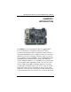
PICO820 Series All-In-One PICO ITX Board User’s Manual CHAPTER 1 INTRODUCTION ® The PICO820 is a Pico-ITX board with support for Intel ATOM™ ® processor Z500 Series, and integrates chipset Intel System Controller Hub US15W that deliver outstanding system performance through high-bandwidth interfaces, multiple I/O functions for interactive applications and various embedded computing solutions.
PICO820 Series All-In-One PICO ITX Board User’s Manual 1.
PICO820 Series All-In-One PICO ITX Board User’s Manual Ethernet One port with RTL8111B for Gigabit/Fast Ethernet One RJ-45 connector Audio HD Audio compliant (with Speaker/line-out & MIC-in) via ALC888 Supports multi-channel audio stream, 32-bit sample depth, and sample rate up to 192KHz Lin-in/Line-out/MIC-in SDIO One SDIO port support SDIO1.1 specification.
PICO820 Series All-In-One PICO ITX Board User’s Manual 1.
PICO820 Series All-In-One PICO ITX Board User’s Manual CHAPTER 2 JUMPERS AND CONNECTORS 2.1 Board Dimensions and Fixing Holes Component Side NOTE The height of Component Side is 18mm.
PICO820 Series All-In-One PICO ITX Board User’s Manual Solder Side NOTE The height of Solder Side is 9mm.
PICO820 Series All-In-One PICO ITX Board User’s Manual 2.
PICO820 Series All-In-One PICO ITX Board User’s Manual Solder Side 8 Jumpers and Connectors
PICO820 Series All-In-One PICO ITX Board User’s Manual 2.3 Jumper Settings Proper jumper settings configure the PICO820 to meet your application purpose. We are herewith listing a summary table of all jumpers and default settings for onboard devices, respectively. Jumper Default Setting Jumper Setting JP1 Flat Panel Power Selection: Optional or Default : 3.3V Short 1-2 JP3 AUTO BUTTON Mode Selection Optional or Default : OFF Short 2-3 JP4 CompactFlash Voltage Selection Optional or Default : 3.
PICO820 Series All-In-One PICO ITX Board User’s Manual 2.3.2 AUTO BUTTON Mode Selection Jumper (JP3) The jumper selects the AUTO BUTTON Mode. Description Function Jumper Setting AUTO BUTTON ON Mode Selection OFF (Default) 2.3.3 CompactFlash™ Power Selection Jumper (JP4) This jumper is to select the voltage for CompactFlash™ interface. Description CompactFlash™ Power Select Function Jumper Setting 3.
PICO820 Series All-In-One PICO ITX Board User’s Manual 2.3.4 CMOS Clear Jumpers (JP5) You may need to use this jumper is to clear the CMOS memory if incorrect settings in the Setup Utility.
PICO820 Series All-In-One PICO ITX Board User’s Manual 2.4 Connectors Connectors connect the board with other parts of the system. Loose or improper connection might cause problems. Make sure all connectors are properly and firmly connected. Here is a summary table shows you all connectors on the PICO820 Series.
PICO820 Series All-In-One PICO ITX Board User’s Manual 2.4.1 VGA Connector (CN1) CN1 is a standard 15-pin DB15 connector commonly for the CRT VGA display. Pin Signal 1 Red 2 Green 3 Blue 4 N.C 5 Ground (GND) 6 AnalogGround(AGND) 7 AnalogGround(AGND) 8 AnalogGround(AGND) 9 N.C 10 Ground (GND) 11 N.
PICO820 Series All-In-One PICO ITX Board User’s Manual 2.4.2 DC POWER JACK Connector (CN2) The CN2 is a DC Power JACK connector for DC 5V input. Pin Signal 1 GND 2 GND 3 +5V 4 +5V 2.4.3 DC POWER Connector (CN3) (Optional) The CN3 (co-lay with CN2) is a 3.96mm wafer DC Power connector for DC 5V input. Pin Signal 1 +5V 2 GND 2.4.4 LPC Interface Connector (CN4) The CN4 is a LPC Interface Connector.
PICO820 Series All-In-One PICO ITX Board User’s Manual 2.4.5 LVDS Flat Panel Connector (CN5) The LVDS connector on the PICO820 is a 40-pin connector. It is strongly recommended to us the matching JST SHDR-40V-S-B connector. Pin Signal Pin Signal 1 VCCM 2 VCCM 3 VCCM 4 VCCM 5 VCCM 6 VCCM 7 N.C. 8 N.C. 9 GND 10 GND 11 N.C. 12 N.C. 13 N.C. 14 N.C. 15 GND 16 GND 17 N.C. 18 N.C. 19 N.C. 20 N.C. 21 GND 22 GND 23 Channel A D0- 24 N.C. 25 Channel A D0+ 26 N.C.
PICO820 Series All-In-One PICO ITX Board User’s Manual 2.4.6 Serial ATA Power Connector (CN6) The CN6 is a 2.5mm wafer connector for Serial ATA Power. Pin Signal 1 +5V 2 GND 2.4.7 Flat Panel Bezel Connector (CN7) Power LED This 3-pin connector denoted as Pin 1 and Pin 5 connects the system power LED indicator to such a switch on the case. Pin 1 is assigned as +, and Pin 5 as -. The Power LED lights up when the system is powered ON.
PICO820 Series All-In-One PICO ITX Board User’s Manual HDD Activity LED This connection is linked to hard drive activity LED on the control panel. LED flashes when HDD is being accessed. Pin 13 and 14 connect the hard disk drive to the front panel HDD LED, Pin 13 assigned as -, and Pin 14 as +. 2.4.8 Digital I/O Connector (CN8) The board is equipped an 8-channel digital I/O connector CN8 that meets requirements for a system customary automation control.
PICO820 Series All-In-One PICO ITX Board User’s Manual W83627HGAW GPIO PIN Number 124 123 122 121 (GP14) (GP15) (GP16) (GP17) GPIO Bit 4 Bit 5 Bit 6 Bit 7 CN8 PIN 6 PIN 7 PIN 8 PIN 9 PIN Define Digital Output 0 Digital Output 1 Digital Output 2 Digital Output 3 2.4.9 LVDS Backlight Connector (CN9) The CN9 is DF13-7S-1.25C 7-pin connectors for inverter that we strongly recommend you to use the matching DF13-7S-1.25C connector.
PICO820 Series All-In-One PICO ITX Board User’s Manual 2.4.10 Thru Front I/O Connector 1 (CN10) Pin Signal Pin Signal Pin Signal 1 +5V SBY 2 +5V SBY 3 USB D0- 4 USB D1- 5 USB D0+ 6 USB D1+ 7 GND 8 GND 9 GND 10 GND 11 +5V SBY 12 +5V SBY 13 USB D2- 14 USB D3- 15 USB D2+ 16 USB D3+ 17 GND 18 GND 19 GND 20 GND 21 KB_VCC 22 K/B Data 23 K/B CLK 24 GND 25 KB_VCC 26 KB_VCC 27 M/S Data 28 M/S CLK 29 GND 30 N.C.
PICO820 Series All-In-One PICO ITX Board User’s Manual 2.4.12 SMBUS Connector (CN12) Connector CN12 is for SMBUS interface support. Pin Signal 1 CLOCK 2 DATA 3 GND 2.4.13 CPLD JTAG Interface Connector (JP2) The JP2 is a 2.0mm Pin header connector for CPLD Interface Connector. Pin Signal 1 +3.3V SBY 2 GND 3 TCK 4 TDO 5 TDI 2.4.14 Ethernet Connector (LAN1) The RJ-45 connector is for Ethernet.
PICO820 Series All-In-One PICO ITX Board User’s Manual 2.4.15 Serial ATA Power Connector (SATA1) The SATA connector SATA1 is for high-speed SATA interface ports, and IT can be connected to hard disk devices. Pin Signal 1 GND 2 SATA_TX+ 3 SATA_TX- 4 GND 5 SATA_RX- 6 SATA_RX+ 7 GND 2.4.
PICO820 Series All-In-One PICO ITX Board User’s Manual 2.4.17 CompactFlash™ Socket (SCN2) TM The board is equipped with a CompactFlash disk type-II socket on TM the solder side that supports the IDE interface CompactFlash disk card with DMA mode supported. The socket is especially designed to TM avoid any incorrect installation of the CompactFlash disk card. TM When installing or removing the CompactFlash disk card, please TM make sure that the system power is off.
PICO820 Series All-In-One PICO ITX Board User’s Manual Pin Signal Pin Signal 24 IOCS16# 49 Data 10 25 CD2# 50 GND 1 2 3 4 5 6 7 8 9 10 11 12 13 14 15 16 17 18 19 20 21 22 23 24 25 26 27 28 29 30 31 32 33 34 35 36 37 38 39 40 41 42 43 44 45 46 47 48 49 50 Jumpers and Connectors 23
PICO820 Series All-In-One PICO ITX Board User’s Manual MEMO 24 Jumpers and Connectors
PICO820 Series All-In-One PICO ITX Board User’s Manual CHAPTER 3 HARDWARE DESCRIPTION 3.1 Microprocessors ® The PICO820 Series supports Intel ATOM™ processor Z500 Series, which make your system operated under Windows 2000/XP, and Linux environment. The system performance depends on the microprocessor. Make sure all correct settings are arranged for your installed microprocessor to prevent the CPU from damages. 3.
PICO820 Series All-In-One PICO ITX Board User’s Manual 3.4 I/O Port Address Map ® The Intel ATOM™ processor Z500 Series can communicate via I/O ports. There are total 1KB port addresses available for assignment to other devices via I/O expansion cards.
PICO820 Series All-In-One PICO ITX Board User’s Manual Address Devices 3B0-3BF MDA video card 3C0-3CF EGA card 3D0-3DF CGA card 3F6 3.5 Forward to SATA (SATA Controller) 3F8-3FF Serial port #1 (COM1) 3E8-3EF Serial port #3 (COM3) 2F8-2FF Serial port #2 (COM2) 2E8-2EF Serial port #4 (COM4) Interrupt Controller The PICO820 Series is a 100% PC compatible control board. It consists of 16 interrupt request lines, and four out of them can be programmable.
PICO820 Series All-In-One PICO ITX Board User’s Manual MEMO 28 Hardware Description
PICO820 Series All-In-One PICO ITX Board User’s Manual CHAPTER 4 PHOENIX-AWARD BIOS UTILITY The Phoenix-Award BIOS provides users with a built-in Setup program to modify basic system configuration. All configured parameters are stored in a battery-backed-up RAM (CMOS RAM) to save the Setup information whenever the power is turned off. 4.1 Entering Setup There are two ways to enter the Setup program.
PICO820 Series All-In-One PICO ITX Board User’s Manual 4.
PICO820 Series All-In-One PICO ITX Board User’s Manual 4.4 The Main Menu Once you enter the Award BIOS CMOS Setup Utility, the Main Menu appears on the screen. In the Main Menu, there are several Setup functions and a couple of Exit options for your selection. Use arrow keys to select the Setup Page you intend to configure then press to accept or enter its sub-menu.
PICO820 Series All-In-One PICO ITX Board User’s Manual 4.5 Standard CMOS Setup Menu The Standard CMOS Setup Menu displays basic information about your system. Use arrow keys to highlight each item, and use or key to select the value you want in each item. Date The date format is , . Press to show the calendar. day It is determined by the BIOS and read only, from Sunday to Saturday. date It can be keyed with the numerical/ function key, from 1 to 31.
PICO820 Series All-In-One PICO ITX Board User’s Manual IDE Primary Master/Primary Slave These items identify the types of each IDE channel installed in the computer. There are 45 predefined types (Type 1 to Type 45) and 2 user’s definable types (Type User) for Enhanced IDE BIOS. Press /<+> or /<> to select a numbered hard disk type, or directly type the number and press . Please be noted your drive’s specifications must match the drive table.
PICO820 Series All-In-One PICO ITX Board User’s Manual 4.6 Advanced BIOS Features This section allows you to configure and improve your system, to set up some system features according to your preference.
PICO820 Series All-In-One PICO ITX Board User’s Manual CPU Feature Scroll to this item and press to view the CPU Feature sub menu. Hard Disk Boot Priority Scroll to this item and press to view the sub menu to decide the disk boot priority.
PICO820 Series All-In-One PICO ITX Board User’s Manual Quick Power On Self Test This option speeds up Power on Self Test (POST) after you turn on the system power. If set as Enabled, BIOS will shorten or skip some check items during POST. The default setting is “Enabled”. Enabled Enable Quick POST Disabled Normal POST First/Second/Third Boot Device These items let you select the 1st, 2nd, and 3rd devices that the system will search for during its boot-up sequence.
PICO820 Series All-In-One PICO ITX Board User’s Manual MPS Version Control For OS This item specifies the version of the Multiprocessor Specification (MPS). Version 1.4 has extended configuration tables to improve support for multiple PCI bus configurations and provide future expandability. Press to return to the Main Menu page. 4.
PICO820 Series All-In-One PICO ITX Board User’s Manual System BIOS Cacheable Selecting Enabled allows caching of the system BIOS ROM at F0000h-FFFFFh, resulting in better system performance. However, if any program writes to this memory area, a system error may result. The default value is “Disabled”. Video BIOS Cacheable This item allows you to change the Video BIOS location from ROM to RAM. Video Shadow will increase the video speed.
PICO820 Series All-In-One PICO ITX Board User’s Manual 4.8 Integrated Peripherals This section allows you to configure your OnChip IDE Device, SuperIO Device and Onboard Device. OnChip IDE Device Scroll to this item and press to view the sub menu OnChip IDE Device.
PICO820 Series All-In-One PICO ITX Board User’s Manual IDE HDD Block Mode Block mode is also called block transfer, multiple commands, or multiple sectors read/write. If your IDE hard drive supports block mode (most new drives do), select Enabled for automatic detection of the optimal number of block read/writes per sector the drive can support. Press to return to the Integrated Peripherals page. Onboard Device Scroll to this item and press to view the sub menu Onboard Device.
PICO820 Series All-In-One PICO ITX Board User’s Manual USB Device Setting Scroll to this item and press to view the sub menu USB Device Setting. Onboard Serial Port 1/2 Select an address and corresponding interrupt for the serial port. There are several options for your selection. Onboard Lan Boot ROM Use this item to enable or disable the Boot ROM function of the onboard LAN chip when the system boots up.
PICO820 Series All-In-One PICO ITX Board User’s Manual 4.9 Power Management Setup The Power Management Setup allows you to save energy of your system effectively. It will shut down the hard disk and turn OFF video display after a period of inactivity. ACPI Function This item allows you to enable/disable the Advanced Configuration and Power Management (ACPI). The function is always “Enabled”.
PICO820 Series All-In-One PICO ITX Board User’s Manual Video Off Method This setting determines the manner in which the monitor is blanked. V/H SYNC+Blank Turns OFF vertical and horizontal synchronization ports and writes blanks to the video buffer DPMS Select this option if your monitor supports the Display Power Management Signaling (DPMS) standard of the Video Electronics Standards Association (VESA). Use the software supplied for your video subsystem to select video power management values.
PICO820 Series All-In-One PICO ITX Board User’s Manual Instant-Off This option follows the conventional manner systems perform when power is turned OFF. Instant-Off is a soft power OFF sequence requiring only the switching of the power supply button to OFF Delay 4 Sec. Upon turning OFF system from the power switch, this option will delay the complete system power OFF sequence by approximately 4 seconds.
PICO820 Series All-In-One PICO ITX Board User’s Manual 4.10 PnP/PCI Configuration Setup This section describes the configuration of PCI (Personal Computer Interconnect) bus system, which allows I/O devices to operate at speeds close to the CPU speed while communicating with other important components. This section covers very technical items that only experienced users could change default settings. Reset Configuration Data Normally, you leave this item Disabled.
PICO820 Series All-In-One PICO ITX Board User’s Manual IRQ Resources When resources are controlled manually, assign each system interrupt to one of the following types in accordance with the type of devices using the interrupt: 1. Legacy ISA Devices compliant with the original PC AT bus specification, requiring a specific interrupt (such as IRQ4 for serial port 1). 2. PCI/ISA PnP Devices compliant with the Plug and Play standard, whether designed for PCI or ISA bus architecture.
PICO820 Series All-In-One PICO ITX Board User’s Manual 4.11 PC Health Status This section supports hardware monitoring that lets you monitor those parameters for critical voltages, temperatures and fan speed of the board. System Component Characteristics These items provide you with information about the system’s current operating status. You can’t change these items. 1. 2. 3. 4.
PICO820 Series All-In-One PICO ITX Board User’s Manual 4.12 Load Optimized Defaults This option allows you to load your system configuration with default values. These default settings are optimized to enable high performance features. To load CMOS SRAM with SETUP default values, please enter “Y”. If not, please enter “N”.
PICO820 Series All-In-One PICO ITX Board User’s Manual 4.13 Set Supervisor/User Password You can set a supervisor or user password, or both of them. The differences between them are: 1. Supervisor password: You can enter and change the options on the setup menu. 2. User password: You can just enter, but have no right to change the options on the setup menu. When you select this function, the following message will appear at the center of the screen to assist you in creating a password.
PICO820 Series All-In-One PICO ITX Board User’s Manual 4.14 Save & Exit Setup This section allows you to determine whether or not to accept your modifications. Type “Y” to quit the setup utility and save all changes into the CMOS memory. Type “N” to bring you back to the Setup utility.
PICO820 Series All-In-One PICO ITX Board User’s Manual 4.15 Exit Without Saving Select this option to exit the Setup utility without saving changes you have made in this session. Type “Y”, and it will quit the Setup utility without saving your modifications. Type “N” to return to the Setup utility.
PICO820 Series All-In-One PICO ITX Board User’s Manual MEMO 52 Installation of Drivers
PICO820 Series All-In-One PICO ITX Board User’s Manual CHAPTER 5 INSTALLATION OF DRIVERS The device drivers are located on the Product Information CD-ROM that comes with the PICO820 Series package. The auto-run function of drivers will guide you to install the utilities and device drivers under a Windows system. You can follow the onscreen instructions to install these devices: Chipset VGA LAN Audio 5.1 Installing Chipset Driver 1. Run the SETUP.
PICO820 Series All-In-One PICO ITX Board User’s Manual ® 2. An Intel License Agreement appears to show you the important information. Click “Yes” to next step. 3. Please wait while running the following setup operations.
PICO820 Series All-In-One PICO ITX Board User’s Manual (3-2) 4. Click “Finish” to complete the setup process.
PICO820 Series All-In-One PICO ITX Board User’s Manual 5. 5.2 You will be asked to reboot your computer when the installation is completed. Please click “Yes, I want to restart my computer now” if you don’t need to install any other drivers. Otherwise, please click “No, I will restart my computer later”, and go on next step. Installing VGA Driver 1. Run the SETUP.EXE program from the driver directory in your driver CD. Click “Next” to next step.
PICO820 Series All-In-One PICO ITX Board User’s Manual ® 2. An Intel License Agreement appears to show you the important information. Click “Yes” to next step. 3. The message of Readme File Information appears to show you the system requirements and installation information. Please click “Next”.
PICO820 Series All-In-One PICO ITX Board User’s Manual 4. Please wait while running the following setup operations. 5. When this message appears, please click “Next”.
PICO820 Series All-In-One PICO ITX Board User’s Manual 6. You will be asked to reboot your computer when the installation is completed. Please click “Yes, I want to restart my computer now” if you don’t need to install any other drivers. Otherwise, please click “No, I will restart my computer later”, and click “Finish” to complete the installation.
PICO820 Series All-In-One PICO ITX Board User’s Manual 5.3 60 Installing LAN Driver 1. Run the InstallShield Wizard for Ethernet from the driver directory in your driver CD. Click “Next” to next step. 2. Click “Install” to start the installation.
PICO820 Series All-In-One PICO ITX Board User’s Manual 3. Please wait while running the following installation operation. 4. Click “Finish” to complete the installation.
PICO820 Series All-In-One PICO ITX Board User’s Manual 5.4 Installing Audio Driver 1. Run the InstallShield Wizard for Audio from the driver directory in your driver CD. Click “Next” to next step.
PICO820 Series All-In-One PICO ITX Board User’s Manual 2. Please wait while running the following installation operation.
PICO820 Series All-In-One PICO ITX Board User’s Manual 3. You will be asked to reboot your computer when the installation is completed. Please click “Yes, I want to restart my computer now” if you don’t need to install any other drivers. Otherwise, please click “No, I will restart my computer later”, and click “Finish” to complete the installation.
PICO820 Series All-In-One PICO ITX Board User’s Manual APPENDIX A WATCHDOG TIMER Watchdog Timer Setting (From Super I/O W83627HG-AW) After the system stops working for a while, it can be auto-reset by the Watchdog Timer. The integrated Watchdog Timer can be set up in the system reset mode by program.
PICO820 Series All-In-One PICO ITX Board User’s Manual Timeout Value Range 1 to 255 Minute / Second Program Sample Watchdog Timer can be set to system reset after 5-second timeout.
PICO820 Series All-In-One PICO ITX Board User’s Manual APPENDIX B DIGITAL I/O Digital I/O Software Programming GPI program sample: O 2E 87 Un-Lock Super I/O O 2E 87 Un-Lock Super I/O O 2E 07 Select Logic device O 2F 07 O 2E F1 Read Data I 2F XX XX is input Data;if no input source,the value is 0F Q Quit debug GPO program sample: O 2E 87 Un-Lock Super I/O O 2E 87 Un-Lock Super I/O O 2E 07 Select Logic device O 2F 07 O 2E F1 Output Data I 2F XX XF=0F,1F,2F,…FF (X is Output Data) Q
PICO820 Series All-In-One PICO ITX Board User’s Manual MEMO 68 Digital I/O