AXIS 210/211 Network Camera User’s Manual
About this Document This manual is intended for administrators and users of the AXIS 210/211 Network Camera, and is applicable for software release 4.20. It includes instructions for using and managing the AXIS 210/211 on your network. Previous experience of networking will be of use when using this product. Some knowledge of UNIX or Linux-based systems may also be beneficial, for developing shell scripts and applications. Later versions of this document will be posted to the Axis Website, as required.
AXIS 210/211 Contents Product Features . . . . . . . . . . . . . . . . . . . . . . . . . . . . . . . . . . . . . . . . . . . . . . . . . . . . . . . . . . . . . . . . . 5 AXIS 211 - Extra Features . . . . . . . . . . . . . . . . . . . . . . . . . . . . . . . . . . . . . . . . . . . . . . 6 Overview . . . . . . . . . . . . . . . . . . . . . . . . . . . . . . . . . . . . . . . . . . . . . . . . . . . . . . . . . . . . 7 Accessing the Camera . . . . . . . . . . . . . . . . . . . . . . . . . . . . . . . . . .
AXIS 210/211 SMTP (email) . . . . . . . . . . . . . . . . . . . . . . . . . . . . . . . . . . . . . . . . . . . . . . . . . . . . . . . . 38 UPnP™ . . . . . . . . . . . . . . . . . . . . . . . . . . . . . . . . . . . . . . . . . . . . . . . . . . . . . . . . . . . . . 39 RTP (multicast) MPEG-4. . . . . . . . . . . . . . . . . . . . . . . . . . . . . . . . . . . . . . . . . . . . . . . 39 Ports & Devices. . . . . . . . . . . . . . . . . . . . . . . . . . . . . . . . . . . . . . . . . . . . . . . . . . . .
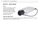
AXIS 210/211 - Product Features Product Features The AXIS 210 and the AXIS 211 are part of the latest generation of fully featured Axis Network Cameras, all based on the AXIS ARTPEC-2 compression chip. The AXIS 211 features a DC-Iris and support for Power over Ethernet (PoE). All instructions and information in this manual are valid for both cameras unless otherwise stated.
AXIS 210/211 - Product Features AXIS 211 - Extra Features DC-Iris The AXIS 211 features a varifocal DC-Iris, which automatically regulates the amount of light entering the camera. Tele/wide and focus are adjusted manually with the aid of the pullers mounted on the lens. Power over Ethernet (PoE) Supporting PoE network transformers conforming to IEEE 802.3af, the AXIS 211 can be powered directly from the network cabling.
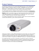
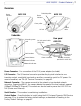
AXIS 210/211 - Product Features Overview Status indicator Tele/wide puller Status indicator AXIS 210 AXIS 211 Focus puller Control cable DC-Iris Underside Mounting screw hole DC-Iris control cable (AXIS 211) Serial number Control button Power connector Power indicator Rear panel AXIS 211 I/O terminal connector Network connector (and PoE for AXIS 211) Network indicator Power Connector - For connection of the PS-K power adapter (included).
AXIS 210/211 - Product Features LED Indicators After completion of the startup and self test routines, the multi-colored Network, Status, and Power LED indicators flash as follows: Network Status Power Amber Steady for connection to 10 Mbit/s network. Flashes for network activity. Green Steady for connection to100 Mbit/s network. Flashes for network activity. Red Flashes rapid red, together with the Status indicator, for hardware error. Unlit No connection.
AXIS 210/211 - Accessing the Camera Accessing the Camera To use the AXIS 210/211 on your network, it must first be installed. Please see the AXIS 210/211 Installation Guide, supplied with the product, or available from www.axis.com The cameras can be used with most standard operating systems and browsers. The recommended browser is Internet Explorer with Windows, and Mozilla with other operating systems. See also the Technical Specifications, on page 49.
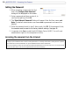
AXIS 210/211 - Accessing the Camera Setting the Password 1. When accessing a camera for the first time, the ‘Configure Root Password’ dialog will be displayed on the screen. 2. Enter a password and then re-enter it, to confirm the spelling. Click OK. 3. The ‘Enter Network Password’ dialog will appear. Enter the User name: root Note: The default administrator user name root is permanent and cannot be deleted. 4. Enter the password as set in step 2 above, and click OK.
AXIS 210/211 - Accessing the Camera Focusing To focus the AXIS 210, simply turn the adjustment ring on the lens until the focus is satisfactory. To focus the AXIS 211, follow the instructions below. 1. From the Basic Configuration page in the setup tools, open the Focus adjustment page. 2. Set the DC-Iris to Disabled and click Save. 3. Unscrew the zoom puller on the lens by turning it anti-clockwise. Adjust the zoom setting as required. Re-tighten the zoom puller.
AXIS 210/211 - Accessing the Camera The Live View Page Depending on whether or not the Live View page has been customized, the buttons described below may or may not be visible. To resize the video image, click the View Size buttons: half-size (x1/2), full-size (x1), x2 or x4. Note that this does not change the video image’s resolution, but simply how it is displayed. Changing the View size is not available in Sequence Mode.
AXIS 210/211 - Accessing the Camera The AMC viewer toolbar (AXIS Media Control) is available in Microsoft Internet Explorer only. It displays the following buttons: The Play/Stop button starts and stops the live video stream. The Snapshot button saves a snapshot of the video image currently being displayed. The Snapshot function and the target directory for saving snapshots can be configured from the AMC Control Applet in the Windows Control Panel (Internet Explorer only).
AXIS 210/211 - Video Streams Video Streams The AXIS 210/211 provides several different image and video stream formats. The type to use depends on your requirements and on the properties of your network. The Live View page in the AXIS 210/211 provides access to Motion JPEG and MPEG-4 video streams, as well as to single JPEG images. Other applications and clients can also access these video streams/images directly, without going via the Live View page.
AXIS 210/211 - Video Streams MPEG-4 protocols and communication methods To deliver live streaming video over IP networks, various combinations of transport protocols and broadcast methods are employed. • RTP (Realtime Transport Protocol) is a protocol that allows programs to manage the real-time transmission of multimedia data, via unicast or multicast. • RTSP (Real Time Streaming Protocol) serves as a control protocol, to negotiate which transport protocol to use for the stream.
AXIS 210/211 - Video Streams RTP/RTSP This unicast method is RTP tunneled over RTSP. This can be used to exploit the fact that it is relatively simple to configure firewalls to allow RTSP traffic. RTP/RTSP/HTTP or RTP/RTSP/HTTPS These two methods can also be used to traverse firewalls. Firewalls are commonly configured to allow the HTTP protocol, thus allowing RTP to be tunneled.
AXIS 210/211 - Video Streams Other MPEG-4 clients Although it may be possible to use other clients to view the MPEG-4 stream, this is not guaranteed by Axis. For some other clients, e.g. QuickTime™ the Video Object Type must be set to Simple. It may also be necessary to adjust the advanced MPEG-4 settings. To assess the video stream from e.g. QuickTime™ the following path can be used: rtsp:///mpeg4/media.
AXIS 210/211 - Configuration Configuration This section describes how to configure the camera, and is intended for product Administrators, who have unrestricted access to all the Setup tools, and Operators, who have access to the settings for Video & Image, Live View Config and Event Configuration. The camera is configured under Setup from a standard browser (see Technical Specifications, on page 49). Accessing the Setup tools Follow the instructions below to access the Setup Tools from a browser. 1.
AXIS 210/211 - Configuration Video and Image settings The following descriptions offer examples of the features available in the cameras. For details of each setting, please refer to the online help available from the setup tools. Click to access the online help. Image Appearance Use these settings to change the image as required. The configuration of the video image and overlays will affect the camera’s overall performance, depending on how it is used and on the available bandwidth.
AXIS 210/211 - Configuration Overlay Settings Use these settings to include a) an image as an overlay, and/or b) the date and time, along with text of your own. Text, date and time overlays Overlay image Text overlays are all included on one line at the top or bottom of the video image. Image overlays can be placed anywhere in the video image. To upload an overlay image, see below.
AXIS 210/211 - Configuration Overlay image requirements: Image Formats Image Size • Windows 24-bit BMP (full color) • Windows 4-bit BMP (16 colors) The height and width of the overlay image in pixels must be exactly divisible by 4. Overlay image limitations: • The maximum overlay image size supported by the camera is 640x480, even when using a lower resolution. The overlay is automatically rescaled along with the image. See also the Technical Specifications, on page 49.
AXIS 210/211 - Configuration AXIS Media Control The AXIS Media Control (AMC) is installed automatically the first time the camera is accessed from a browser. The AMC control panel can be opened by right-clicking on the video image in the Live View web page. The AMC control panel can be used to configure various video settings. Please see the readme file included in the tool for more information.
AXIS 210/211 - Live View Config Live View Config Layout These are the tools for deciding the layout of the Live View page. The layout can be set in 3 ways: • Use Axis look - the layout is unchanged. • Use custom settings - modify the Axis look, with your own colors, images etc. Click the Configure button and see below. • Own Home Page - Upload and use your own custom page as the default web page. Click the Configure button and see below. The other settings on this page mainly concern which features (e.g.
AXIS 210/211 - Live View Config Upload Own Web Files Your own web files, background pictures, etc., must first be uploaded to the camera in order to be available for selection in the Custom Settings setup dialog. Once uploaded, the files are shown in the drop-down lists. 1. Click the Upload/Remove button. 2. Enter the path to the file, e.g. a file located on your workstation or click the Browse button. 3. Select the user level for the uploaded file.
AXIS 210/211 - Live View Config User-defined Links Enter a descriptive name and enter the URL in the provided field. Example 1. Check Show Custom Link 1 2. Enter a descriptive name, e.g. My Website 3. Check the radio button for web link. 4. Enter the web link: e.g. http://www.example.com and then click Save. This link will then be shown on the Live View page and will open the specified website. User-defined link User-defined CGI links can be used to issue advanced commands via the Axis HTTP API.
AXIS 210/211 - Live View Config Default Video Format in Internet Explorer for Windows Select the default format to use on the Live View page. Checking the box for Show video format selection displays a drop-down list on the Live View page allowing you to temporarily change the format. When using MPEG-4 as the video format, the default viewer is AXIS Media Control with Internet Explorer. Note: It is also possible to view Motion JPEG when MPEG-4 is chosen as default, and vice versa.
AXIS 210/211 - Live View Config External Video The camera can also display video images from other Axis network cameras and video servers. These are known as External Video sources. Each external video source is available from the drop-down list on the Live View page. Click the Add button to open the External Video Source Setup dialog, which is used to make all the necessary settings. Enter the IP address or host name of the external video source you wish to add.
30 AXIS 210/211 - Event Configuration Event Configuration An event in the camera is when an Event Type is activated and causes certain actions to be performed. The event type is the set of parameters (or conditions) that specifies how and when which actions will be performed. A common event type is when the camera uploads images when an alarm occurs. Many event types use an Event Server, to e.g. upload images to. This section describes how to set up event servers and event types, i.e.
AXIS 210/211 - Event Configuration Configuring Event Types An Event Type describes how and when the camera will perform certain actions. Example: If somebody passes in front of the camera and an event that uses motion detection has been configured to act on this, the camera can e.g. record and save images to an FTP server, and/or send a notification email to a pre-configured email address with a pre-configured message. Images can be sent as email attachments.
32 AXIS 210/211 - Event Configuration Pre-trigger and Post-trigger buffers This function is very useful when checking to see what happened immediately before and/or after a trigger, e.g. 30 seconds before and/or after a door was opened. Check the Upload images checkbox under Event Types > Add Triggered... > Triggered by... to expand the web page with the available options. All uploaded images are JPEG images.
AXIS 210/211 - Event Configuration Motion Detection The motion detection feature is used to generate an alarm whenever movement occurs (or stops) in the video image. A total of 10 Include and/or Exclude windows can be configured.
34 AXIS 210/211 - Event Configuration 7. Click Save. To exclude parts of the Include window, click the Configure Excluded Windows button and position the Exclude window as required, within the Include window. Please see the online help for descriptions of each available option.
AXIS 210/211 - System Options System Options Security User access control is enabled by default. An administrator can set up other users, by giving these user names and passwords. It is also possible to allow anonymous viewer login, which means that anybody may access the Live View page, as described below: Users - the user list displays the authorized users and user groups (levels): Viewer Provides the lowest level of access, which only allows access to the Live View page.
36 AXIS 210/211 - System Options Date & Time Current Server Time - displays the current date and time (24h clock). The time can be displayed in 12h clock format in the Overlay Images (see below). New Server Time - Select your time zone from the drop-down list. If you want the server clock to automatically adjust for daylight savings time, select the Automatically adjust for daylight saving time changes. This adjustment works for all methods.
AXIS 210/211 - System Options Services Options for notification of IP address change - if the IP address for the video server changes, e.g. automatically by DHCP, you can choose to be notified of the change. Click Settings... and enter the required information. AXIS Internet Dynamic DNS Service - If the AXIS 210/211 Video Server has been registered with the Axis Internet Dynamic DNS service and the IP address for the product changes, the service is updated to reflect the change.
38 AXIS 210/211 - System Options Link-Local Address This is enabled by default and assigns the AXIS 210/211 an additional IP address for use with UPnP™. The AXIS 210/211 can have both a Link-Local IP and a static/DHCP-supplied IP address at the same time - these will not affect each other. HTTP The default HTTP port number (80) can be changed to any port within the range 1024-65535. This is useful for e.g. simple security port mapping.
AXIS 210/211 - System Options UPnP™ The AXIS 210/211 includes support for UPnP™, which is enabled by default. If also enabled on your computer, the camera will automatically be detected and a new icon will be added to “My Network Places.” Note: UPnP must also be enabled on your Windows XP or ME computer. To do this, open the Control Panel from the Start Menu and select Add/Remove Programs. Select Add/Remove Windows Components and open the Networking Services section.
40 AXIS 210/211 - System Options Backup - To take a backup of all of the parameters, and any user-defined scripts, click this button. If necessary, it will then be possible to return to the previous settings, if settings are changed and there is unexpected behavior. Restore - click the Browse button to locate the saved backup file (see above) and then click the Restore button. The settings will be restored to the previous configuration.
AXIS 210/211 - System Options Resetting to the Factory Default Settings To reset the camera to the original factory default settings, go to the System Options > Maintenance web page (as described in Maintenance, on page 39) or use the Control button on the underside of the camera (see page 7) as described below: Using the Control Button To reset the camera to the factory default settings using the Control Button: 1. Disconnect the power adapter, or the network cable if using PoE (AXIS 211 only). 2.
42 AXIS 210/211 - The I/O Terminal Connector The I/O Terminal Connector Pinout and Interface The 4-pin I/O terminal connector provides the interface to: • 1 transistor output • 1 digital input • auxiliary power and GND The terminal connector is used in applications for e.g. motion detection, event triggering, time lapse recording, alarm notification via email, image storage to FTP locations, etc. • Input - for connecting e.g. a doorbell.
AXIS 210/211 - The I/O Terminal Connector Connect input/output devices to the terminal connector as follows: 1. Loosen the corresponding screw on top of the pin (see above for the correct pin to use). 2. Push the cable into the connector and secure it by fastening the screw. 3. Once devices are connected, connect the terminal connector to the camera, making sure that all cables are securely fastened. Schematic Diagram - Terminal Connectors 3.
44 AXIS 210/211 - Troubleshooting Troubleshooting Checking the Firmware One of your first actions when troubleshooting a problem should be to check the currently installed firmware version. The latest version may contain a correction that fixes your particular problem. The current firmware version in your camera can be seen on the page Setup > Basic Configuration. Upgrading the Firmware Firmware is software that determines the functionality of the camera.
AXIS 210/211 - Troubleshooting Emergency Recovery Procedure If power or the network connection to the camera is lost during the upgrade, the process will fail and the unit will become unresponsive. A flashing red Status LED indicates a failed upgrade. To recover the unit, follow the steps below. The serial number is found on the label attached to the bottom of the camera. 1.
46 AXIS 210/211 - Troubleshooting Symptoms, Possible Causes and Remedial Actions Problems setting the IP address When using ARP/Ping. Try the installation again. The IP address must be set within two minutes after power has been applied to the camera. Ensure the Ping length is set to 408. See the Installation Guide. The camera is located on a different subnet.
AXIS 210/211 - Troubleshooting Video/Image problems, general Image too dark or too light. Check the video image settings. See the online help on Video and Image Settings. Missing images in uploads. This can occur when trying to use a larger image buffer than is actually available. Try lowering the frame rate or the upload period. Slow image update. Configuring, e.g. pre-buffers, motion detection, high-resolution images, high frame rates, etc, will reduce the performance of the camera.
48 AXIS 210/211 - Troubleshooting The Status and Network indicator LEDs are flashing red rapidly Hardware failure. Contact your Axis dealer. The Status indicator LED is flashing red and the camera is inaccessible A firmware upgrade has been interrupted or the firmware has otherwise been damaged. See the Emergency Recovery Procedure above. No images displayed on web page Problem with AMC.
AXIS 210/211 - Technical Specifications Technical Specifications Item Specification Models • AXIS 210 • AXIS 211 Video compression • Motion-JPEG, including single snapshot JPEG images • MPEG-4 Part2 (ISO/IEC 14496-2), Profiles: ASP and SP Resolutions • 5 resolutions (640x480, 480x360, 320x240, 240x180, 160x120) available from configuration web page • Total 16 resolutions (including PAL/NTSC formats) available via the HTTP API, see www.axis.
50 AXIS 210/211 - Technical Specifications Item Specification Processors and memory • CPU: ETRAX-100 LX 32-bit • Video processing and compression: ARTPEC-2 chip • RAM memory - 16 MB • Flash memory - 4 MB Power over Ethernet (AXIS 211 only) Support for Power over Ethernet according to IEEE802.3af standard, including Power classification according to class 0 (max: 12.95W). Connection via RJ-45 network socket. Operating conditions • Temperature: +5oC (41oF) to +45oC (113oF) • Humidity: 20-80% RHG.
AXIS 210/211 - Technical Specifications General performance considerations When setting up your system, it is important to consider how various settings and situations will affect performance. Some factors affect the amount of bandwidth (the bit rate) required, others can affect the frame rate, and some will affect both. If the load on the CPU reaches its maximum, this will also affect the frame rate.
52 AXIS 210/211 - Technical Specifications Frame rates - Motion JPEG and MPEG-4 The following table shows typical frame rates in frames/second (fps) for Motion JPEG and MPEG-4 video streams from the AXIS 210/211. Note that these values are guidelines only - actual values may vary.
54 AXIS 210/211 - Glossary of Terms Glossary of Terms ActiveX - A control (or set of rules) used by a browser. ActiveX controls are often downloaded and installed automatically as required. AMC - AXIS Media Control. The control required for viewing video images in Internet Explorer. Installs automatically on first use. API - Application Programming Interface. The Axis API can be used for integrating Axis products into other applications. ARP - Address Resolution Protocol.
AXIS 210/211 - Glossary of Terms switch (see below). RTP- Real-Time Transfer Protocol. A transfer protocol designed for delivery of live contents, e.g. MPEG-4. Simplex - In simplex operation, a network cable or communications channel can only send information in one direction. SMTP - A common e-mail protocol. Subnet Mask - An IP address consists of two components: the network address and the host address.
56 AXIS 210/211 - Index Index A Action 30 Action Buttons 12, 27 Active/Inactive 12, 27 Administrator 18 Administrators 35 Alarm 33, 42 AMC 9 AMC Viewer Toolbar 13 Auxiliary Power 42 AXIS Media Control 24 B Backup 40 Bandwidth 52 Basic Configuration 19 Buffer Size 32 Buffers 32 C CGI links 27 Configuration 18 Control Button 7, 41 Customize 25 D Date & Time 36 DC Power 42 Default Viewer 28 DNS Configuration 37 DNS Server 37 Domain Name 37 E Emergency Recovery 45 Event Servers 30 Event Types 31 Event
AXIS 210/211 - Index 57 Pre-trigger Buffer 32 Pulse 12, 27 T R Recovery 45 Referrals 35 Restore 39, 40 TCP Server 30 TCP/IP Settings 36 Terminal Block 42 Time Mode 36 Triggered Event 30 Troubleshooting 44 S U Scheduled Event 30, 32 Security 35 Sequence Mode 12, 29 Server Time 36 Services 36 Setup Tools 19 Snapshot button 12 Support 40 System Options 35 System Options Overview 20 Upgrade Server 39 Uploading web files 26 User Defined Links 26 Users 19, 35 V Video Stream 22 View Size 12