AXIS 210/210A/211/211A Network Cameras User’s Manual
About this Document This manual is intended for administrators and users of the AXIS 210/210A/211/211A Network Camera and applies to firmware release 4.30. It includes instructions for using and managing the AXIS 210/210A/211/211A on your network. Previous experience of networking will be of use when using this product. Some knowledge of UNIX or Linux-based systems may also be beneficial, for developing shell scripts and applications.
AXIS 210/210A/211/211A Contents Introduction . . . . . . . . . . . . . . . . . . . . . . . . . . . . . . . . . . . . . . . . . . . . . . . . . . . . . . . . . . . . . . . . . . . . 5 Product features . . . . . . . . . . . . . . . . . . . . . . . . . . . . . . . . . . . . . . . . . . . . . . . . . . . . . . 5 Extra features . . . . . . . . . . . . . . . . . . . . . . . . . . . . . . . . . . . . . . . . . . . . . . . . . . . . . . . . 6 Overview . . . . . . . . . . . . . . . . . . . . . . . . . . . . . . . .
AXIS 210/210A/211/211A System Options . . . . . . . . . . . . . . . . . . . . . . . . . . . . . . . . . . . . . . . . . . . . . . . . . . . . . . . . . . . . . . . . . 38 Security . . . . . . . . . . . . . . . . . . . . . . . . . . . . . . . . . . . . . . . . . . . . . . . . . . . . . . . . . . . . 38 Date & Time . . . . . . . . . . . . . . . . . . . . . . . . . . . . . . . . . . . . . . . . . . . . . . . . . . . . . . . . 40 Network - Basic TCP/IP Settings . . . . . . . . . . . . . . . . . . . . . . . .
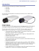
AXIS 210/210A/211/211A - Introduction Introduction This manual covers the following Axis Network Camera models: • • • • AXIS 210 AXIS 210A AXIS 211 AXIS 211A All instructions and information in this manual are valid for all four models unless otherwise stated. Product features The AXIS 210/210A/211/211A cameras are part of the latest generation of fully featured Axis Network Cameras, and are all based on the AXIS ARTPEC-2 compression chip. The most basic model of the four is the AXIS 210.
AXIS 210/210A/211/211A - Introduction • Built-in web server that provides full access to all features via a standard web browser. • Built-in scripting tool that allows the creation of basic applications. For advanced functionality, the cameras can be accessed via the AXIS HTTP API (more info at www.axis.com/developer). Extra features DC-Iris (AXIS 211/211A only) The AXIS 211/211A features a varifocal DC-Iris, which automatically regulates the amount of light entering the camera.
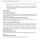
AXIS 210/210A/211/211A - Introduction Overview AXIS 210/AXIS 210A AXIS 211/AXIS 211A Tele/wide puller Status indicator Status indicator DC-Iris control cable Focus puller Focus puller DC-Iris Underside Internal Microphone AXIS 210A/211A Mounting screw hole Serial number Control button Power indicator Network indicator Rear panel DC-Iris control cable (AXIS 211/211A) I/O terminal connector External microphone/line input 210A/211A Audio output 210A/211A Power connector Network connector (and PoE 2
AXIS 210/210A/211/211A - Introduction Power Connector - For connection of the PS-K power adapter (included). I/O Terminal Connector - The I/O terminal connector provides the physical interface to one transistor output, one digital input and an auxiliary connection point for DC power. For more information, see The I/O Terminal Connector, on page 47. Network Connector - The camera connects to the network via a standard network connector.
AXIS 210/210A/211/211A - Accessing the Camera Accessing the Camera Follow the instructions in the AXIS 210/210A/211/211A Installation Guide to install your camera. The cameras can be accessed with most standard operating systems and browsers. The recommended browser is Internet Explorer for Windows, and Mozilla with other operating systems. See also the Technical Specifications, on page 49.
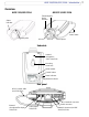
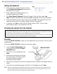
AXIS 210/210A/211/211A - Accessing the Camera Setting the Password 1. When accessing a camera for the first time, the ‘Configure Root Password’ dialog will be displayed on the screen. 2. Enter a password and then re-enter it, to confirm the spelling. Click OK. 3. The ‘Enter Network Password’ dialog will appear. Enter the User name: root Note: The default administrator user name root is permanent and cannot be deleted. 4. Enter the password as set in step 2 above, and click OK.
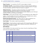
AXIS 210/210A/211/211A - Accessing the Camera The Live View Page Depending on whether or not the Live View page has been customized, the buttons described below may or may not be visible. To resize the video image, click the View Size buttons: half-size (x1/2), full-size (x1), x2 or x4. Note that this does not change the video image’s resolution, but simply how it is displayed. Changing the View size is not available in Sequence Mode.
AXIS 210/210A/211/211A - Accessing the Camera The Live View toolbar displays the following buttons: The Play/Stop button starts and stops the live video stream. The Snapshot button saves a snapshot of the video image currently being displayed. The Snapshot function and the target directory for saving snapshots can be configured from the AMC Control Applet in the Windows Control Panel (Internet Explorer for Windows only).
AXIS 210/210A/211/211A - Video Streams Video Streams The AXIS 210/210A/211/211A provides several different image and video formats. The type to use depends on your requirements and on the properties of your network. The Live View page in the AXIS 210/210A/211/211A provides access to Motion JPEG and MPEG-4 video streams, as well as to single JPEG images. Other applications and clients can also access these video streams/images directly, without going via the Live View page.
AXIS 210/210A/211/211A - Video Streams MPEG-4 protocols and communication methods To deliver live streaming video over IP networks, various combinations of transport protocols and broadcast methods are employed. • RTP (Realtime Transport Protocol) is a protocol that allows programs to manage the real-time transmission of multimedia data, via unicast or multicast. • RTSP (Real Time Streaming Protocol) serves as a control protocol, to negotiate which transport protocol to use for the stream.
AXIS 210/210A/211/211A - Video Streams Unicasting should be used for video-on-demand broadcasting, so that there is no video traffic on the network until a client connects and requests the stream. However, as more and more unicast clients connect, the traffic on the network will increase and may cause congestion. Although there is a maximum of 20 unicast viewers, note that all multicast users combined count as 1 unicast viewer. RTP/RTSP This unicast method is RTP tunneled over RTSP.
AXIS 210/210A/211/211A - Video Streams Other MPEG-4 clients Although it may be possible to use other clients to view the MPEG-4 stream, this is not guaranteed by Axis. For some other clients, e.g. QuickTime™ the Video Object Type must be set to Simple. It may also be necessary to adjust the advanced MPEG-4 settings. To assess the video stream from e.g. QuickTime™ the following path can be used: rtsp:///mpeg4/media.
AXIS 210/210A/211/211A - Video Streams Accessing the Audio Streams In addition to accessing audio in the Live View page using AMC, audio from the AXIS 210A/211A can also be accessed in the following ways: HTTP API You can read about accessing audio for the other protocols through the HTTP-API at http://www.axis.com/techsup QuickTime/Windows Media Player It is possible to use QuickTime and Windows Media Player to listen to the audio stream using the same methods to access video streams.
AXIS 210/210A/211/211A - Setup Tools Setup Tools This section describes how to configure the cameras, and is intended for product Administrators, who have unrestricted access to all the Setup tools, and Operators, who have access to the settings for Video & Image, Audio, Live View Config and Event Configuration. The camera is configured under Setup from a standard browser (see Technical Specifications, on page 49).
AXIS 210/210A/211/211A - Video & Image settings Video & Image settings The following descriptions offer examples of the features available in the AXIS 210/210A/211/211A. For details of each setting, please refer to the online help available to access the online help. from the setup tools. Click Image Settings Image Appearance Adjust these settings to optimize the video images according to your requirements.
AXIS 210/210A/211/211A - Video & Image settings Text Overlay Settings Include date, time and/or text of your choice to be viewed on the image. The color of the text may be set to white or black, while background color may be set to white, black, transparent or semitransparent. The position of the text is set either to the top or the bottom of the image. Video Stream Define the maximum video stream time per session in seconds, minutes or hours.
AXIS 210/210A/211/211A - Video & Image settings Upload and use an overlay To upload an overlay image to the camera: 1. Select Uploaded image as overlay in the drop-down list for Overlay/Mask Type. New options appear. 2. In the field Upload own image, click the Browse button and locate the image file on your computer or server. 3. Click the Upload button and follow the on-screen instructions. To use an already uploaded image: 1. Select an uploaded image from the Use image drop-down list. 2.
AXIS 210/210A/211/211A - Video & Image settings Advanced Settings These pages provide various settings for fine-tuning the video image. Note that the advanced settings available depend on the camera model. Camera Settings To compensate for the lighting conditions, the white balance and exposure control can be adjusted. If available, DC-Iris should always be enabled except during focusing, or when using a non-DC-Iris lens.
AXIS 210/210A/211/211A - Video & Image settings MPEG-4 Settings Tools for adjusting the MPEG-4 settings and for controlling the video bit rate. The MPEG-4 standard provides many different coding tools for various applications in different situations. As most MPEG-4 clients do not support all of these tools, it is usual to instead define and use subsets for different clients or groups of clients. These settings allow you to define the type of viewing client to use.
AXIS 210/210A/211/211A - Audio (AXIS 210A/211A only) Audio (AXIS 210A/211A only) The AXIS 210A/211A can transmit audio to other clients using an external microphone and can play audio received from other clients by attaching a speaker. The Setup page for the AXIS 210A/211A has an additional menu item called Audio, which allows different audio configurations to be set up, e.g. full duplex, half duplex and simplex.
AXIS 210/210A/211/211A - Audio (AXIS 210A/211A only) Full-duplex mode means you can transmit and receive audio (talk and listen) at the same time, without having to use any of the controls. This is just like having a telephone conversation. The only controls you may wish to use are the mute buttons to turn off the sound, and the sliders, to adjust the input/output volume levels. This mode requires the client PC to have a sound card with full-duplex audio support. If your available bandwidth is 0.
AXIS 210/210A/211/211A - Audio (AXIS 210A/211A only) If there are problems with the sound input being too low or high, adjust the input gain for the microphone attached to the AXIS 210A/211A. Audio Output If the sound from the speaker is too low or high, adjust the output gain for the active speaker attached to the AXIS 210A/211A. When satisfied with the settings, click Save, or click Reset to revert to the previously saved settings.
AXIS 210/210A/211/211A - Audio (AXIS 210A/211A only) There are two adjustable parameters available for noise cancellation: • Noise canceller threshold level • Noise canceller attenuation When the incoming sound is louder than the threshold it will pass without being affected. When lower than the threshold, the incoming sound will be reduced by a certain attenuation factor. The threshold level should be set higher than the background noise, but lower than the useful audio.
AXIS 210/210A/211/211A - Live View Config Live View Config These are the tools for deciding the layout of the camera’s Live View page. The layout can be set in 3 ways: • Use Axis look - the layout is unchanged. • Use custom settings - modify the default Live View page with your own colors, images etc. Click the Configure button and see below. • Own Home Page - Use your own custom page as the default web page. Click the Configure button and see the following page.
AXIS 210/210A/211/211A - Live View Config Upload Own Web Files Your own background pictures, banners and logos can either be located externally on e.g. a network server, or they can be uploaded to the AXIS 210/210A/211/211A itself. Once uploaded, files are shown in the drop-down lists for Own (file). Follow these instructions to upload a file. 1. Click the Upload/Remove button in the Custom settings dialog. 2. Enter the path to the file, e.g. a file located on your computer or click the Browse button. 3.
AXIS 210/210A/211/211A - Live View Config User-defined CGI links can be used to issue advanced commands via the Axis HTTP API. For more information, see the Developer pages at www.axis.com/developer Action Buttons The manual trigger buttons can be used to manually trigger and stop an event from the Live View page. See Event Configuration, on page 33. Enabling the display of the Snapshot button allows users to save a snapshot from the video stream by clicking the button.
AXIS 210/210A/211/211A - Live View Config When using any other browser than Internet Explorer for Windows, select the appropriate method from the drop-down list for viewing images. The available options are similar to Internet Explorer except for Server Push. With this method, the camera maintains and controls an open HTTP connection to the browser and sends data as and when required for as long as required.Please see the online help for more information.
AXIS 210/210A/211/211A - Live View Config Select the desired video sources and enter the time in seconds to display each source (up to 59 minutes). Click Save. The Sequence buttons will appear on the Live View page to enable the viewer to start and stop the sequence mode. Please see the online help for more information.
AXIS 210/210A/211/211A - Event Configuration Event Configuration An event in the camera is when an Event Type is activated and causes certain actions to be performed. The event type is the set of parameters (or conditions) that specifies how and when which actions will be performed. A common event type is when the camera uploads images when an alarm occurs. Many event types use an Event Server, to e.g. upload images to. This section describes how to set up event servers and event types, i.e.
AXIS 210/210A/211/211A - Event Configuration Configuring Event Types An Event Type describes how and when the camera will perform certain actions. Example: If somebody passes in front of the camera and an event that uses motion detection has been configured to act on this, the camera can e.g. record and save images to an FTP server, and/or send a notification e-mail to a pre-configured e-mail address with a pre-configured message. Images can be sent as e-mail attachments.
AXIS 210/210A/211/211A - Event Configuration Pre-trigger and Post-trigger buffers This function is very useful when checking to see what happened immediately before and/or after a trigger, e.g. 30 seconds before and/or after a door was opened. Check the Upload images checkbox under Event Types > Add Triggered... > Triggered by... to expand the web page with the available options. All uploaded images are JPEG images.
AXIS 210/210A/211/211A - Event Configuration Motion Detection Motion detection is used to generate an alarm whenever movement occurs (or stops) in the video image. A total of 10 Include and/or Exclude windows can be configured.
AXIS 210/210A/211/211A - Event Configuration Please see the online help for descriptions of each available option.
AXIS 210/210A/211/211A - System Options System Options Security User access control is enabled by default, when the administrator sets the root password on first access. An administrator can set up other users, by giving these user names and passwords.
AXIS 210/210A/211/211A - System Options Notes: •If the referrals feature is enabled and you wish to also allow normal access to the Live View page, the product's own IP address or host name must be added to the list of allowed referrers. •Restricting referrers has no effect on an MPEG-4 video stream. To restrict an MPEG-4 stream, IP address filtering must be enabled. •Restricting referrers is of greatest value when not using IP address filtering.
AXIS 210/210A/211/211A - System Options Date & Time Current Server Time - displays the current date and time (24h clock). The time can be displayed in 12h clock format in the Overlay Images (see below). New Server Time - Select your time zone from the drop-down list. If you want the server clock to automatically adjust for daylight savings time, select the Automatically adjust for daylight saving time changes.
AXIS 210/210A/211/211A - System Options Services Options for notification of IP address change - if the IP address for the video server changes, e.g. automatically by DHCP, you can choose to be notified of the change. Click Settings... and enter the required information. AXIS Internet Dynamic DNS Service - The AXIS Internet Dynamic DNS Service can provide your Axis product with its own URL (web address), which can then be used to access it over the Internet.
AXIS 210/210A/211/211A - System Options Link-Local Address This is enabled by default and assigns the AXIS 210/210A/211/211A an additional IP address for use with UPnP™. The AXIS 210/210A/211/211A can have both a Link-Local IP and a static/DHCP-supplied IP address at the same time - these will not affect each other. HTTP The default HTTP port number (80) can be changed to any port within the range 1024-65535. This is useful for e.g. simple security port mapping.
AXIS 210/210A/211/211A - System Options Network Traffic The default setting is Auto-negotiate which means that the correct speed is automatically selected. If necessary, you can set the connection speed by selecting it from the drop-down list. Maximum bandwidth - Specify, in Mbit/s or kbit/s, the maximum bandwidth the AXIS 210/210A/211/211A will be allowed to use on your network. This is a useful function when connecting the camera to busy or heavily loaded networks. The default setting is Unlimited.
AXIS 210/210A/211/211A - System Options Network - UPnP™ The cameras includes support for UPnP™, which is enabled by default. If also enabled on your computer, the camera will automatically be detected and a new icon will be added to “My Network Places.” Note: UPnP must also be enabled on your Windows XP or ME computer. To do this, open the Control Panel from the Start Menu and select Add/Remove Programs. Select Add/Remove Windows Components and open the Networking Services section.
AXIS 210/210A/211/211A - System Options Backup - To take a backup of all of the parameters, and any user-defined scripts, click this button. If necessary, it will then be possible to return to the previous settings, if settings are changed and there is unexpected behavior. Restore - click the Browse button to locate the saved backup file (see above) and then click the Restore button. The settings will be restored to the previous configuration.
AXIS 210/210A/211/211A - System Options Plain Config - this function is for the advanced user with previous experience of configuring Axis cameras. All parameters can be set and modified from this page. Help is available via the links on the standard setup pages.
AXIS 210/210A/211/211A - The I/O Terminal Connector The I/O Terminal Connector Pinout and Interface The 4-pin I/O terminal connector provides the interface to: • 1 transistor output • 1 digital input • auxiliary power and GND The terminal connector is used in applications for e.g. motion detection, event triggering, time lapse recording, alarm notification via e-mail, image storage to FTP locations, etc. • Input - for connecting e.g. a push button.
AXIS 210/210A/211/211A - The I/O Terminal Connector Connect input/output devices to the terminal connector as follows: 1. Loosen the corresponding screw on top of the pin (see above for the correct pin to use). 2. Push the cable into the connector and secure it by fastening the screw. 3. Once devices are connected, connect the terminal connector to the camera, making sure that all cables are securely fastened. Schematic Diagram - Terminal Connectors 3.
AXIS 210/210A/211/211A - Technical Specifications Technical Specifications Item Specification Models • AXIS 210 • AXIS 210A: Power over Ethernet, audio • AXIS 211: Power over Ethernet, DC-iris • AXIS 211A: Power over Ethernet, DC-iris, audio Video compression • Motion-JPEG • MPEG-4 Part2 (ISO/IEC 14496-2), Profiles: ASP and SP Resolutions Frame rates 16 resolutions (640x480 to 160x120) via API, 5 selections via configuration web page.
AXIS 210/210A/211/211A - Technical Specifications Item Specification Processors, memory, clock • CPU: ETRAX 100LX 32bit • Video processing and compression: ARTPEC-2 • RAM memory: 16 MB (AXIS 210/211) 32 MB (AXIS 210A/211A) • Flash memory: 4 MB (AXIS 210/211) 8 MB (AXIS 210A/211A) • Battery backed up real-time clock Power • 7-20V DC, max 5W • Power over Ethernet (IEEE 802.3af), power classification Class 0 (AXIS 211) or Class 2 (AXIS 210A/211A) (max 6.
AXIS 210/210A/211/211A - Technical Specifications Item Specification System integration support • Powerful API for software integration available at www.axis.com • Event trigger data in video stream • AXIS Media Control SDK • Embedded scripting support • Watchdog secures continuous operation, can be monitored by other systems via event notification • Embedded operating system: Linux 2.
AXIS 210/210A/211/211A - Technical Specifications General performance considerations When setting up your system, it is important to consider how various settings and situations will affect performance. Some factors affect the amount of bandwidth (the bit rate) required, others can affect the frame rate, and some will affect both. If the load on the CPU reaches its maximum, this will also affect the frame rate.
AXIS 210/210A/211/211A - Technical Specifications Frame rates - Motion JPEG and MPEG-4 The following table show typical frame rates in frames/second (fps) for Motion JPEG and MPEG-4 video streams from the AXIS 210/210A/211/211A. Note that these values are guidelines only - actual values may vary.
AXIS 210/210A/211/211A - Troubleshooting Troubleshooting Checking the Firmware One of your first actions when troubleshooting a problem should be to check the currently installed firmware version. The latest version may contain a correction that fixes your particular problem. The current firmware version in your camera can be seen on the page Setup > Basic Configuration. Upgrading the Firmware Firmware is software that determines the functionality of the camera.
AXIS 210/210A/211/211A - Troubleshooting Emergency Recovery Procedure If power or the network connection to the camera is lost during the upgrade, the process will fail and the unit will become unresponsive. A flashing red Status LED indicates a failed upgrade. To recover the unit, follow the steps below. The serial number is found on the label attached to the bottom of the camera. 1.
AXIS 210/210A/211/211A - Troubleshooting Symptoms, Possible Causes and Remedial Actions Problems setting the IP address When using ARP/Ping. Try the installation again. The IP address must be set within two minutes after power has been applied to the camera. Ensure the Ping length is set to 408. See the Installation Guide. The camera is located on a different subnet.
AXIS 210/210A/211/211A - Troubleshooting Video/Image problems - general No images in browser (Internet Explorer for Windows only) To enable the updating of video images in Microsoft Internet Explorer for Windows, set your browser to allow ActiveX controls. Also, make sure that AXIS Media Control (AMC) component is installed on your workstation. Installation of additional ActiveX com- Configure your camera to use a Java applet for updating the video images under ponent restricted or prohibited.
AXIS 210/210A/211/211A - Troubleshooting Poor rendering of MPEG-4 images. Color depth set incorrectly on clients. Set to 16-bit or 32-bit color. If text overlays are blurred, or if there are other rendering problems, you may need to enable Advanced Video Rendering. This is done on the MPEG-4 tab in the AMC control panel applet. Ensure that your graphics card is using the latest device driver. The latest drivers can usually be downloaded from the manufacturer's web site.
AXIS 210/210A/211/211A - Troubleshooting Full duplex not supported. Sound card does not support full-duplex. For information on how to check if your sound card supports full-duplex, please visit http://support.microsoft.com Firewall or router settings. The AXIS 210A/211A works locally, but not externally. Check the Internet firewall settings with your system administrator or reconfigure the default router settings. DC power not enabled for microphone.
AXIS 210/210A/211/211A - Glossary of Terms Glossary of Terms Active Speaker - a speaker with a built-in power amplifier. ActiveX - A control (or set of rules) used by a browser. ActiveX controls are often downloaded and installed automatically as required. ADPCM - Adaptive Differential Pulse Code Modulation. Predicts the analog signal digitally and the difference is coded. AMC - AXIS Media Control. The control required for viewing video images in Internet Explorer for Windows.
AXIS 210/210A/211/211A - Glossary of Terms NWAY - A network protocol that automatically negotiates the highest possible common transmission speed between two devices. PAL - Phase Altering Line. PAL is the standard format used for televisions in most of the world (other than the US, Canada, and Japan). PCM - Pulse Code Modulation. Analog signal converted directly to a digital.
AXIS 210/210A/211/211A - Index Index A Accessing the video stream 15 Action 33 Action Buttons 11, 30 Active/Inactive 30 Administrator 18 Advanced Simple profile 13 Alarm 36, 47 AMC Viewer Toolbar 12 Audio 24 Audio input 25 Audio mode 24 Audio output 26 Auxiliary Power 47 AXIS 15 AXIS Media Control 15, 25 B Backup 45 Bandwidth 13, 53 Bit rate 13 Buffer Size 35 Buffers 35 C CGI links 30 Control Button 8, 46 Custom settings 28 D Event Types 34 Events 33 External Video 31 External Video Source 11 F
AXIS 210/210A/211/211A - Index 63 Network Settings 40 NTP Configuration 41 NTP Server 40 O Other MPEG-4 clients 16 Output 47 Output Buttons 30 Output buttons 11 Own home page 29 Own web files 29 P Pinout - I/O connectors 47 PoE 6, 8 Port Status 37 Ports & Devices 44 Post-trigger Buffer 35 Power Connector 8 Power over Ethernet 6 Pre-trigger Buffer 35 Pulse 11, 30 Push to talk 25 R Recovery 55 Referrals 38 Restore 44, 45 RTP 14 RTSP 14 S Scheduled Event 33, 35 Security 38 Sequence Mode 11, 31 Sequence
AXIS 210/210A/211/211A - Index
AXIS COMMUNICATIONS Quick User’s Guide AXIS 210/210A/211/211A User’s Manual Rev. 4.