
- Axis Network Camera User's Manual 223M
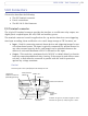
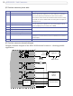
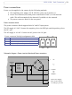
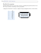
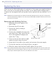
Table Of Contents
- Product Features
- Accessing the Camera
- Video Streams
- Setup Tools
- Video and Image Settings
- Audio
- Live View Config
- Event Configuration
- System Options
- Security - Users
- Security - 802.1x
- Date & Time
- Network - Basic TCP/IP Settings
- Network - Advanced TCP/IP Settings
- Network - SOCKS
- Network - QoS (Quality of Service)
- Network - SMTP (email)
- Network - SNMP
- Network - UPnP™
- Network - RTP (Multicast)/MPEG-4
- Network - Bonjour
- Ports & Devices
- LED Settings
- Maintenance
- Support
- Advanced
- About
- Resetting to the factory default settings
- Unit Connectors
- Troubleshooting
- Replacing the lens
- Technical Specifications
- Glossary of Terms
- Index
53
AXIS 223M - Unit Connectors
Power connections
Power can be supplied to the camera by the following methods:
• The supplied power adapter, PS-K, 9W. The center pin is positive (+).
• Power over Ethernet (PoE) with power classification Class 2, via the network
cable. This will automatically be detected if available via the network.
• The power connector block on the rear panel.
Power connector block
The power connector block supports both AC and DC input power.
The DC supply is 7-24V. Connect the negative pole to the GND pin and the positive pole to
the DC+ pin.
The AC supply is 10-24V. Connect the AC poles to the AC pins.
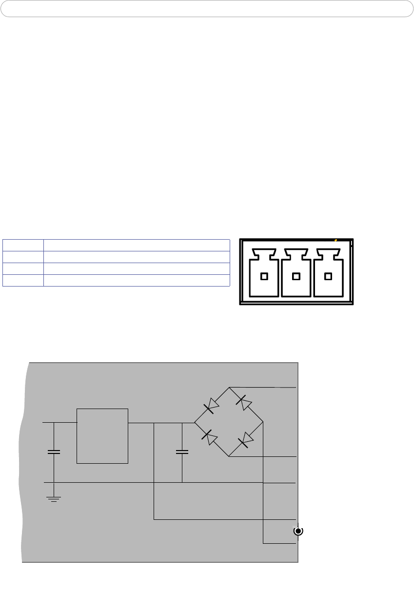
Schematic diagram - Power terminal block and Power connectors
Power connector block pin assignment table.
Pin Function
GND Ground/DC-
AC/DC+ AC and DC+, power input for mains power to unit
AC AC power input for mains power to unit
AC AC
DC+
GND
3
2
o
o
Mode
Power
Supply
3.3V
z
z
zz
z
z
z
z
z
z
o
o
Internal
~
Switch
o
z
GND
AC
1
AC/DC+
GND/DC-
=
+
-
Axis Power Supply
PS-K 9V max 9W or
according to parts list