
User Guide

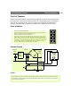
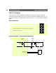
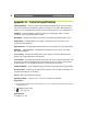
Table Of Contents
- An Introduction to the AXIS 2420
- Physical Description
- Checking The Hardware Inventory
- Installing on a Network
- Installing via a Modem
- Focusing Your Camera
- Configuring Your Camera
- The Factory Default Settings
- Choosing Your Application
- The AXIS 2191 Audio Module
- Appendix A - Troubleshooting
- Appendix B - Other IP Setup Methods
- Appendix C - Lenses and Advanced Focusing
- Appendix D - Customizing Your Camera
- Appendix E - Updating the Firmware
- Appendix F - The Unit Connectors
- Appendix G - High-Speed Services
- Appendix H - Technical Specifications
- Physische Beschreibung
- Überprüfen des Lieferumfangs
- Installieren in einem Netzwerk
- Anschließen an ein Modem
- Scharfeinstellung der Kamera
- Werkseitige Standardeinstellungen
- Description du Materiel
- Vérification de la liste du matériel
- Installation sur un réseau
- Installation par l’intermédiaire d’un modem
- Mise au point de votre caméra
- Restauration des paramètres d’usine par défaut
- Descripción física
- Comprobar el inventario de hardware
- Instalación de la cámara a una red
- Instalación de la cámara a un módem
- Enfocando la cámara
- Incluir los parámetros por defecto
- Index
AXIS 2420 User’s Manual The Unit Connectors
67
The DC-Iris Connector
The AXIS 2420 can be used with any standard C/CS lens. With full support for standard
DC-Iris lenses, the camera will automatically regulate the amount of light entering the
camera.
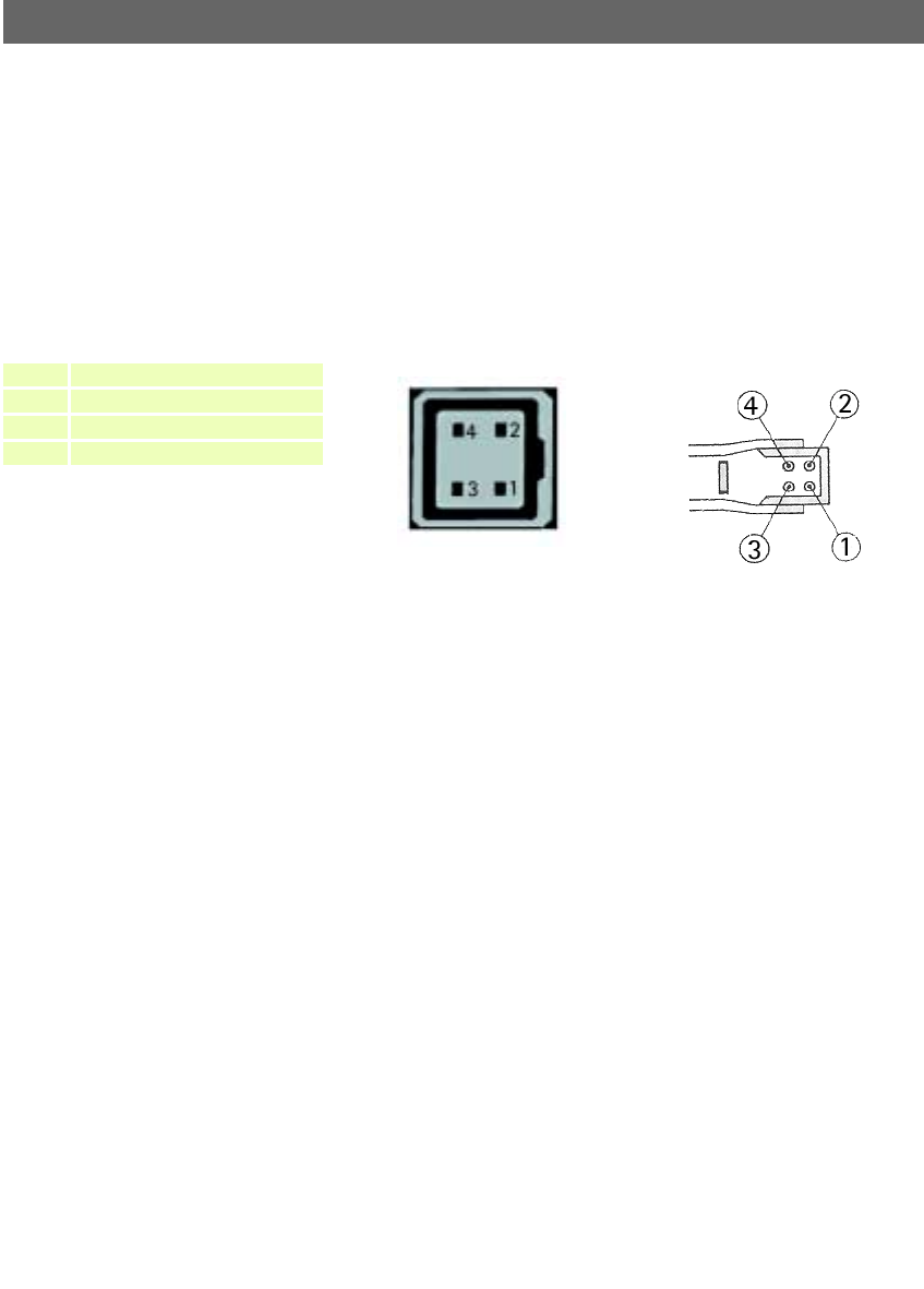
The DC-Iris Connector provides the power and control signalling required for a DC-Iris
lens. The connector is located on the rear panel and the pinout for the connector is shown
below.
The BNC Video Output
The BNC Video Output can be used for connecting the AXIS 2420 to a traditional analog
CCTV system or to a VCR. This output can be used independently of the Ethernet network
connector and both can be used at the same time. The output conforms to 1.0V (p-p) 75
Ohms, sync negative.
The Ethernet Network Connector
The RJ-45 network connector is used to connect the AXIS 2420 to a 10/100Mbit Ethernet
network running TCP/IP.
Control and Monitoring
You can enable IO Status to display ON/OFF buttons for driving the Digital Output from
the Layout section of the Administration Tools on the Home Page of the AXIS 2420.
By entering http requests in your browser’s URL field, you can:
• drive the relay output high or low
• monitor the status of the digital input
Pin Function
1 Control and detection (-)
Socket on rear of camera
Soldering side of connector
2 Control and detection (+)
3 Motor (+)
4 Motor (-)