
User's Manual

AXIS 225FD - Unit Connectors
35
Unit Connectors
This section describes the following:The I/O terminal block
•LED indicators
• Power connection
I/O Terminal Block
The 7-pin I/O terminal connector provides the interface to a
solid state relay output, two digital inputs, RS-485/422 and
GND.
The terminal connector is used in
applications for e.g. motion
detection, event triggering, time lapse recording, alarm
notification via email, image storage to FTP locations, etc.
• Input - Used for
connecting external alarm devices
and triggering images for specific alarm-based events.
The input is typically connected to a motion detector
or any other external security device, and images can
be uploaded whenever the detector is activated. Con-
nect to GND to activate.
• Output - This can
drive a maximum load of 50VDC or
35VAC at 100mA directly or heavier loads by connect-
ing additional relay circuitry
. If the output is used
with an external relay, a diode must be connected in
parallel with the load for protection against any volt-
age transients.
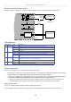
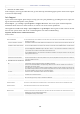
I/O terminal connector block pinout:
Pin Function Description
1 Output A On the external device output terminals (A and B), there is no distinction between positive and nega-
tive (+ and -). The terminals use a photocoupler and are
electrically isolated from the other internal
circuitry.
The maximum load should not exceed 100mA and the maximum voltage shoul
d be not more than
50VDC or 35VAC.
2 Output B
3 Digital Input 1 Connect to GND to activate, or leave float
ing (or unconnected) to deactivate.
4 Digital Input 2
5 RS-485/422-A
(non-inverting)
A half-duplex RS-485 interface for controll
ing auxiliary equipment.
6 RS-485/422-B
(inverting)
7 GND Ground.
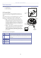
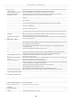
Network
connector
Control
Conduit hole
and plug
LED
indicators
1
2
3
4
1
7
button
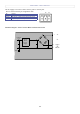
Power connector block
I/O terminal
block
G
N
D
+
o
r
AC
A
C