
Installation Guide


Page 4 AXIS 207/207W/207MW Installation Guide
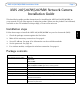
Hardware overview
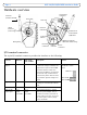
I/O terminal connector
The 4-pin I/O terminal connector provides the interface to the following:
Function AXIS 207
AXIS 207W
AXIS 207MW
Description Pinouts
Transistor
Output
Pin 4 Pin 4 With a maximum load of 100mA and
a maximum voltage of 24V DC, this
output has an open-collector NPN
transistor with the emitter con-
nected to the GND pin. If used with
an external relay, a diode must be
connected in parallel with the load,
for protection against voltage tran-
sients.
The I/O terminal pins are
numbered as shown
below.
Digital Input Pin 3 Pin 3 Connect to GND to activate, or leave
floating (or unconnected) to deacti-
vate.
GND Pin 2 Pin 1
Auxiliary DC
Power Input
Pin 1
(5VDC
min 2.5W)
Pin 2
(5VDC
min 3.5W)
Connected electrically in parallel
with the power adapter, this pin
provides an auxiliary connector for
mains power to the unit. It can also
be used to power auxiliary equip-
ment, max 50mA.
Focus ring
Status
indicator
(outer ring)
Microphone
Antenna
(wireless models)
Network
connector
Network
indicator
Control
button
Lock ring
Product ID &
serial number
(S/N) label
Wireless indicator
Power
indicator
I/O terminal
connector
Power
connector
(Wireless models only)
1
4
1
4
AXIS 207W
AXIS 207MW
AXIS 207