
Instruction manual

The AXIS 2191 Audio Module AXIS 2400+/2401+ Admin Manual
34
Technical Specifications for the AXIS 2191
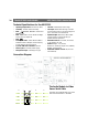
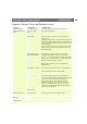
Connection Diagram
The Audio Module to Video
Server Serial Cable
The serial cable supplied with your AXIS
2191 is wired as shown in the table:
• Operating temperature: 40-105
o
F (5-40
o
C).
• Humidity - 8-80% relative humidity.
• EMC - : EN55024, EN55022, Class B and
EN61000-3-3.
• EMC - FCC Class A of FCC Rules and Regu-
lations part 15, subpart B.
• EMC -
• Full-duplex audio: Audio data encoded in
ADPCM format at 32kbps, 8 kHz sampling
(G.721). Data is sent using HTTP.
• 9-pin D-SUB serial connector: RS-232.
• Power Input: Axis PS-D power supply.
• Microphone Input: 1-50mVpp. PC type.
• Line Out: Unbalanced, 0.05-1.0Vpp
• Line Input: Balanced 0.05-1Vpp. Connect
source ground to pin 2 and source signal to
pin 1 if the source is unbalanced.
• Speaker Output: Balanced, 0.5W. Imped-
ance 8-32 Ohms. Connect directly to
speaker without capacitors.
• Alternative Power: 12-15VAC, min 10VA,
or 15-20VDC, min 7W.
• Metrics: Height: 1.1” (27mm),
Width: 4.4” (112mm), Length: 4.3” (110mm),
Weight: 0.7lb (0.32kg).
• Maximum number of users: 10 (on local
area network).
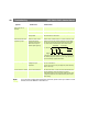
Pinouts for the RS-232 Port
Audio Pin Pin Server Signal
IN 1 1 IN CD
IN 2 2 IN RXD
OUT 3 3 OUT TXD
OUT 4 4 OUT DTR
GND 5 5 GND GND
IN 6 6 IN DSR
OUT 7 7 OUT RTS
IN 8 8 IN CTS
Unused 9 9 IN RI