
Instruction manual

The I/O Terminal Block AXIS 2400+/2401+ Admin Manual
50
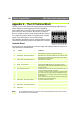
Appendix G - The I/O Terminal Block
Typically used in association with programming scripts for developing applications for
motion detection, event triggering, time lapse recording,
alarm notification via e-mail, picture storage to FTP locations
and a variety of other functions; the 16-pin I/O Terminal
Block is located on the rear panel and provides the interface
to: a single relay switch output, four digital photo-coupled
inputs, an RS-485 interface, and auxiliary power.
This appendix describes the pinout, interface support and the
control and monitoring functions provided by this connector.
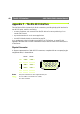
Connector Pinout
The pinout for the Terminal Block (illustrated right) and signaling details for each pin is
fully described in the table below:
Note: For compatible replacement connectors, contact http://www.phoenixcontact.com, quoting:
MC1.5/8-ST-3.81 (art no 1803633).
Pin Function Description
1 Auxiliary AC Power Input Electrically connected in parallel with PS-D power connector, pins 1 & 2
provide an auxiliary connector for mains power to the unit.
2 Auxiliary AC Power Input
3 Digital Input 3 - Photocoupler Anode (+) Photocoupled Input 3: Electrically isolated from the chassis and connec-
tors, this input can be supplied from an external DC voltage or the DC
Power Input/Output on pins 9 and 10.
4 Digital Input 3 - Photocoupler Cathode (-)
5 Digital Input 4- Photocoupler Anode (+) Photocoupled Input 4. As above.
6 Digital Input 4 - Photocoupler Cathode (-)
7 RS-485 - B (inverting) Serial Port 1- RS-485. A half-duplex RS-485 interface for controlling
auxiliary equipment. Note: Serial Port 1 is programmed as either
RS-232 (COM1 Connector) or RS-485 (Terminal Block Connector), via
the browser interface.
8 RS-485 - A (non-inverting)
9 DC + Power (Input or Output) DC Power Input or Output: Used as an input, this supplies the unit via a
DC source; for example a solar panel or a battery.
As an output, it can drive the photo coupler inputs or other equipment;
such as an IR-sensor. The output voltage level is dependent upon the
input voltage to the unit. A maximum current of 50mA can be sourced
from the DC output.
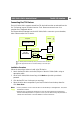
Pin 10 is connected to the unit chassis, and Ground on each serial port
and video input. See circuit diagram (below).
10 DC - Power (Input or Output)
11 Digital Input 1 - Photocoupler Anode (+) Input 1 Photo coupler input. As Input 3.
12 Digital Input 1 - Photocoupler Cathode (-)
13 Digital Input 2 - Photocoupler Anode (+) Input 2 Photo coupler input. As Input 3.
14 Digital Input 2 - Photocoupler Cathode (-)
15 Relay Switch Relay switch - electrically isolated from chassis and connectors.
16 Relay Switch