
Instruction manual


AXIS 2400+/2401+ Admin Manual Product Description
7
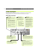
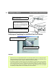
AXIS 2401+ Front Panel
DIP Switch
A single line termination for the
supported video output. Units are
shipped with the line termination
enabled; that is, with the DIP
switch set in the down-position.
If the AXIS 2401+ is to be con-
nected in parallel with other
equipment, disable the input ter-
mination by turning the corre-
sponding DIP switch to the
up-position (OFF). Failure to do so
can cause the picture quality to
be impaired.
Serial Number
Located on the underside label of the AXIS
2401+, the serial number is identical to the
unit’s MAC/Ethernet address.
Status Indicator
The multi-colored status indicator
defines the operational status of the
server, as described below:
• green - the indicator flashes briefly
and momentarily displays orange
during the start-up and self-test
routines; the indicator then displays
green to indicate a healthy unit sta-
tus.
• red - the indicator will display red
only if a problem with the AXIS
2401+ has occurred
• orange - flashes orange when reset-
ting the factory default settings.
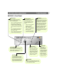
Network Indicator
After completion of the startup
and self test routines, the
multi-colored Network Indica-
tor flashes independently, as
follows:
• yellow - indicating network
activity on a 10Mbps
Ethernet network
• green - indicating network
activity on a 100Mbps Fast
Ethernet network
• red - indicating no physical
connection to the network.
Power Indicator
The Power indicator is normally lit while
power is applied. If it is not lit, or it
flashes, there is a problem with the AXIS
2401+ external power source.
Control Button
This button is recessed
within the product casing.
Using a suitably pointed
object, press this button to
restore the factory default
settings. For further infor-
mation, refer to Network
Settings, on page 17.
Video Input
Coaxial BNC connector support-
ing a single video source. The
physical connection is made using
RG59, 75 Ohm coax video cable;
with a recommended maximum
length of 800 feet (250 meters).
Video Output
A single video
loopthrough (VIDEO
OUT) connected in
parallel with VIDEO IN
and terminated with a
coax/BNC connector.
Allows direct connec-
tion of an external
monitor. Set dipswitch
to OFF when in use.