
User Guide

The Unit Connectors AXIS 2490 User’s Manual
32
Appendix D - The Unit Connectors
This section provides a detailed overview of the Serial Server’s serial port connections: the
two RS-232 Serial Ports, and the IO Block Connector, including the RS-422/485 Port.
The Serial Connectors
The two RS-232 serial connectors provide the physical interface for connecting serial
devices to the AXIS 2490 and thus to the network.
RS-232 Connections
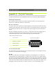
Two 9 pin male D-sub connectors provide the physical connections for the RS-232 serial
interface of the AXIS 2490. These connectors are for use with serial devices at speeds of up
to 115200 bps. The RS-232 ports (3 outputs and 5 inputs) support all status and control
signals.
The male connector is the same as on a PC, i.e. a DTE. The RS-232 driver supports up to
115200 bps. Wiring distances should be limited to about 60 meters (200 feet) for
asynchronous data and to about 15 meters (50 feet) on synchronous lines.
The IO Connector Block
The AXIS 2490 has an I/O Connector (screw terminal blocks) for connecting RS-485/422,
or for use as an alternative power supply.
RS-485
RS-485 is a bi-directional, half-duplex standard for transmitting data over multi-drop
communications line. Supporting up to 32 drivers and 32 receivers over a single twisted
pair cable, the maximum cable length should not exceed 1220 meters (4000 feet). Typically
used for connecting a single master (e.g. a PC) to several addressable devices over the same
cable. The master decides which slave speaks and the slaves only speak when spoken to, by
raising RTS. The Axis 2490 will act as either a master or a slave, depending on how
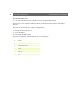
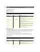
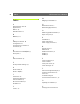
COMx D-SUB 9 connector (RS-232 levels)
Pin Function
1 I CD (Carrier Detect) The Pinout for the male RS-232
connector on the Serial Server
2 I RXD (Receive Data)
3 O TXD (Transmit Data)
4 O /DTR (Data Terminal Ready)
5 - GND (Ground)
6 I /DSR (Data Set Ready)
7 O /RTS (Request To Send)
8 I /CTS (Clear To Send)
9 I /RI (Ring Indicator)
5
3
2
7
14
8
96