Product Instructions 25733 & 25735 C O M M U N I C A T I O N S Before attempting to connect or operate this product, please read these instructions completely.
IMPORTANT SAFEGUARDS 1. Read Instructions - All the safety and operating instructions should be read before the unit is operated. 2. Retain Instructions - The safety and operating instructions should be retained for future reference. 3. Heed Warnings - All warnings on the unit and in the operating instructions should be adhered to. 4. Follow Instructions - All operating and user instructions should be followed. 5. Electrical Connections - Only a qualified electrician should make electrical connections. 6.
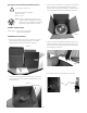
ELECTRICAL SPECIFICATIONS (OUTDOOR ONLY): ! 3, Open the dome assembly box. Note there is a protection film on the dome. DO NOT REMOVE the film until the product is fully assembled and installed. This film protects the dome from scratches during installation. (Picture 3) Power 24VAC, Class 2 Only 26 watts at 24 VAC (accessories) Heater: 25 watts Blower: 1 watt NOTE: This unit is designed for operation in an upright position.
Installing Axis 213 Camera 1. Install the camera onto the quick release bracket using (2) 10-32 x 3/8” screws and star washers provided in the packet. ½" Attach cameras using these inserts 2. In the kit there are (8) aluminum spacers - (4) 1" and (4) ½". Thread (2) spacers - (1) 1" and (1) ½" - on top of each of the (4) 2" spacers that are already located on the base bracket inside the housing. ½" + 1" spacers 1" 2" 3.
Installing Axis 213 Camera (cont.) CAMERA POWER Connect the power plug and the ethernet cable to the back of the camera. For Model 21893 only If alarm connections are needed use the chart below for reference.
Installing Axis 214 Camera 2685 Mounting Plate: Attach camera using these (3) holes 2" 3. Place (3) 8 x 32 x s Phillips head screws on the top of the spacer as shown above. Be sure to place the screws so that they line up with the open slots on the mounting plate. 4. Slide the mounting plate with camera into position on top of spacers. Secure 3 screws and captive fastener. 1. Install the AXIS 214 camera to the 2685 mounting plate using the (3) 3mm x 12mm bolt and lock washers provided. 2.
Installing Axis 231D/232D Camera 1. Install the camera onto the quick release bracket. Loosen one of the screws on the bottom of the camera, see diagram below. 4. When the locking buttons hit the end of the keyhole slots. Tighten the locking screw. Then put the camera assembly aside. Locking screw Loosen screw 2. Place quick release bracket onto the bottom of the camera, making sure that the (3) locking buttons line up with the keyhole slots Keyhole slots in the Q/R bracket.
Installing Axis 231D/232D Camera (cont.) 7. Then start (3) 8-32x3/8” plillips head screws onto the 3 inch spacers inside the housing. Be sure to place the screws so that they line up with the (3) open slots on the quick release bracket, the screws on the bottom of the camera, see diagram below. 10. Locate the connector block, which is included with the camera. Then located the connector block bracket, which is included with the housing. Attach the block to the bracket as shown in the following diagram.
Installing Axis 231D/232D Camera (cont.) 13. To manage the input cable running from the connector block to the camera use the (2) cable tie mounts and cable ties that are located in the housing packet. Cable Tie Mounts 12. Make wiring connections to connector block assembly per camera instructions.
Installing Axis 231D/232D Camera (cont.) 14. Now grab the camera assembly and connector the RJ45 cable and the input cable to the camera. 15. Now attached the camera assembly to the housing by sliding the (3) open screw slots over the screws in the housing. Slide the bracket forward, and the tighten the captive screw on the bracket.
Installing Axis 233 Camera Keyhole Slots 1. Note the position of the mounting holes on the camera bracket (see diagram below). Mounting holes 4. Place the Quick Release plate onto the bottom of the camera, Make sure that the locking screws on the AXIS 233 camera line up with the keyhole slots on the Q/R plate. Mounting holes 2. Now attach (4) ½” spacers (located in the packet Slide the camera into the keyhole slots by targeting the locking screw(s). that came with the housing) to the base bracket.
Chart A Wiring Color Code Power and Control Inputs (Outside of housing) POWER WIRING Two plug-in wall transformers are included with the housing. Use one to provide power for the heater and blower in the housing, and the other for the camera. Determine where the transformers will be located, then run two sets of power wires into the wall mount bracket (Four total power wires). Use the chart below to determine the correct gauge of wire needed based on the length of the run and the 30vA power line.
INSTALLING THE HOUSING ASSEMBLY: ! REMOVING AND ATTACHING THE DOME ASSEMBLY: Be sure the bracket is properly and securely mounted to a supporting structure capable of rigidly holding the weight of the entire unit. 1. Attach the dome assembly to the housing top by lining up the arrow on the dome assembly with the left arrow on the housing top.
Exploded View for Replacement Parts 15 14 9 8 7 6 4 5 3 2 1 - 14 -
Replacement Parts List Part Number Description 1 RPFD7501 LOWER TRIM RING (Long) 2 25740 TINTED REPLACEMENT CAPSULE 25741 CLEAR REPLACEMENT CAPSULE 3 RPFD703 DOME CLAMPING BRACKET 4 RPFD072 24 VAC HEATER 5 RPFD080 BLOWER 6 RPFD060 CAMERA BRACKET 7 RPRH707 CONNECTION PCB 8 RPFD040 HOUSING HARDWARE 9 RPFD709 HOUSING TOP 14 SD0160 PENDANT COUPLING KIT 15 SD0170 QUICK RELEASE PIPE COUPLING N/S RPNET02 24 TO 12VDC POWER BOARD - 15 -