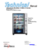
Glassfront BevMax 3 5800-4 Vender Model DN5800 - 4 Production Run 8882AH & higher Operation Service Parts Troubleshooting Manual Manufactured by Dixie-Narco, Inc. P.O. Drawer 719 Williston, SC 29853-0719 803-266-5001 fax: 803-266-5049 Visit us on the web: www.dixienarco.com 803,904,620.
Table of Contents GENERAL INFORMATION.................................................................................. 4 Vender Safety Precautions..................................................................................................4 Product Identification ...........................................................................................................4 Physical Characteristics ......................................................................................................
Picker Cup at Wrong Location X Axis Flow Chart .............................................................41 Delivery Port Door Flow Chart...........................................................................................42 Coin Acceptance................................................................................................................43 Bill Acceptors .....................................................................................................................
VENDER SAFETY PRECAUTIONS Please read this manual in its entirety. This service information is intended for use by a qualified service technician who is familiar with proper and safe procedures to be followed when repairing, replacing or adjusting any Dixie-Narco vender components. All repairs should be performed by a qualified service technician who is equipped with the proper tools and replacement components, using genuine Dixie-Narco factory parts.
WARNING: TO AVOID THE POSSIBILITY OF A FIRE HAZARD, DO NOT STORE ANYTHING OR ALLOW DEBRIS OF ANY KIND TO ACCUMULATE IN THE BOTTOM OF THE SERVICE AREA, IN AND AROUND THE REFRIGERATION COMPARTMENT OF THE CABINET, OR IN FRONT OF THE EVAPORATOR AND CONDENSER COILS. into the plug or mounted on the cord adjacent to the plug. WARNING: ENSURE THAT POWER IS DISCONNECTED FROM THE VENDER BEFORE INSPECTING OR REPLACING THE LAMPS, OTHER ELECTRICAL COMPONENTS, OR WORKING WITH OR ADJUSTING THE VENDING MECHANISM.
provided with the machine. DO NOT USE THE VENDING MACHINE UNTIL THE WORN OR DAMAGED CORD IS REPLACED. FAILURE TO COMPLY WITH THESE INSTRUCTIONS MAY SUBJECT THE USER TO THE RISK OF INJURY OR ELECTRICAL SHOCK WHICH CAN BE SERIOUS OR FATAL. PERIODICALLY INSPECT THE POWER SUPPLY CORD FOR DAMAGE. IF THE CORD BECOMES DAMAGED IT MUST BE REPLACED WITH THE SAME SIZE AND TYPE CORD. CONTACT DIXIE-NARCO FOR ASSISTANCE.
acceptor should cycle twice). The display on the door will briefly show the software version in use as “Software ###.## (ie 70#.#1) followed by the default idle message “ENJOY A REFRESHING DRINK”, the fluorescent lamp should be lit and the cooling unit should start. If the display shows “OUT OF SERVICE”, or the cooling unit fails to start, refer to the TROUBLESHOOTING SECTION beginning on page 31. pallet jack or Vender/Cooler Dollies at all times when moving the Vender.
WARNING TO AVOID THE POSSIBILITY OF A FIRE HAZARD, DO NOT STORE ANYTHING OR ALLOW DEBRIS OF ANY KIND TO ACCUMULATE IN THE BOTTOM OF THE DOOR, IN THE BOTTOM OF THE SERVICE AREA, IN AND AROUND THE REFRIGERATION COMPARTMENT OF THE CABINET, OR IN FRONT OF THE EVAPORATOR AND CONDENSER COILS. INSTALLING PRICE LABELS Pricing labels included in the literature package kit.
fill/dispense mode in the test menu. (see page 19 in the programming section for more information). For additional information about coin mechanism, refer to the manufacturer’s instructions. POWER AC DISTRIBUTION BOX The power distribution box is where the 120VAC input voltage is broken down to the main operating voltages of the vender (24 VAC and 12 VAC) by a transformer. Those voltages are sent to the controller via the P1 (3 pin) connector.
DELIVERY (PICKER) CUP ASSEMBLY The delivery (picker) cup assembly is located on the XY vend mechanism. Its purpose is to pick the product from the column and deliver the product to the delivery port assembly. The delivery (picker) cup assembly is mounted on the XY assembly and bolts in position. The X axis runs left to right. The X axis assembly is cabinet mounted to prevent any cabinet torque and has one belt to synchronize the top and bottom when the X moves left or right.
PROGRAMMING GENERAL INFORMATION In order to fully utilize the many features of your vender it is important that you first understand the options available and procedures for programming the vending controller unit (control board). All programming, testing, and service functions are accomplished by using the keypad in an easy to follow, display prompted format. In stand alone operation there are four modes of operation for servicing, testing, and setting up your vender.
“” and display will show “PR $##.## B(tray letter) Row Set”, press “*” to set more prices or CLR to return to SET PRICES. Press CLR Key again to return to SERVICE MODE. 3. Single selection. Press the keypad numbers of the price you wish to use. As numbers are entered the numbers will shift in from the right as they are entered. Note: The CLR key will remove the last # of the price. Once the desired price is showing on the display press the selection desired for setting price.
BevMax 3 5800-4 Z Board Programming A B C D E F 1 2 3 4 5 6 7 8 9 Service Mode Step through below Cash Box Sales Display Temperature Set Refrig. Temp. Clear Totals Number Sold Enable Item (Disable) Sales by Column Escrow Force Vend Set Temp.
SERVICE MODE MENU ITEMS Note: Menu items with the ** are not currently available. SERVICE MODE Enter SERVICE MODE by opening the service door and pressing the Service button once. The display will read “SERVICE MODE”. The following choices are now available: NEXT ITEM - Press key “A” CASH BOX - Press key “B” Shows the amount of change diverted to the cash box from the coin mechanism since the last CLEAR TOTALS or MASTER RESET.
1. Pressing the “” key will toggle between enabled and disabled for the entire machine, the display will show the new state i.e. enabled or disabled and display will show “Blocked (Unblocked) Continue? = Y CLR = N. 2. Pressing a tray selection followed by “” will show the new state of that tray. (For example, pressing “A*” will show the new state for the A tray, the display will show the new state i.e. enabled or disabled and display will show “A Blocked (Unblocked) Continue? = Y CLR = N. 3.
B(tray letter) Row Set”, press “*” to set more prices or CLR to exit to SET PRICE. 3. Single selection. Press the keypad numbers of the price you wish to use. As numbers are entered the numbers will shift in from the right as they are entered. Note: The CLR key will remove the last # of the price. Once the desired price is showing on the display press the selection desired for setting price. Press “” and display will show “PR $##.
LB – Low battery. CTRL PWR OUT – Power lost. KEYPAD ERROR KEYPAD – Keypad not installed. COIN MECH ERROR CM CC – Coin Mech disconnected. CM TS – Tube Sensor defective. CM IC – No coin accepted for 96 hours (4 days). CM TJXX – Tube jam. CM CRCH – Check sum. CM EE – Excessive escrow pressed (255 times between coin arrivals). CM NJ – Coin jam. CM LA – Low acceptance count. CM DIS – Acceptor unplugged. CM ROUT – Coin routing error. NOTE ACCEPTOR ERROR NA BC – Note Acceptor disconnected. NA BFUL – Stacker full.
• • • setting. Cup Sensor On is used in all BevMax 3 5800-4 Venders produced 3/26/08 and after. Key 1 = Position Test. Note: The left or top door switch (depending on the mounting bracket in use) must be pulled to the out position to perform this test. Caution: XY needs to be in the home position before performing this test. If you look at the control board the green, amber (yellow), and red lights should be on at this time.
LED on the controller also will be on when a “1” is displayed. “Hm” indicates whether the picker home switch is closed. A “1” indicates that the picker home switch is closed (plunger at home position) and a “0” indicates it is opened. This switch is moved by the plunger, pulling the plunger out by hand will turn the switch off. The Red LED on the controller will also be on when a “1” is displayed. • • • • • • • Key 4 = Repeat Vend.
• Australian Rules. If enabled, the VCU will set the clock back one hour on the last Sunday of March (1:00 AM), set the clock ahead one hour on the first Sunday in October (1:00 AM). Press the “CLR” key to return to “Daylight Savings Time”. Press the “CLR” key to return to “TEST MODE” or press the “A” key to advance to the next menu item below. NOT AVAILABLE MODE - Press key “3” This setting works in conjunction with the “SET NOT AVAILABLE TIME” (option 3 in Setup Mode 1).
TEST VEND - Press key “9” Allows the service technician to test vend any item. The service door must be closed or open all the way so the discharge door does not hit the delivery cup during the test vend process. You will need to catch the product if you test with door open. Press the number “9” on the keypad and the display will read “TEST VEND”. Pull the top door switch in service door area to the out position for this test to work.
MASTER RESET - Press key “F” (PASSWORD REQUIRED) Allows the service technician to restore factory defaults to the machine or reset the Controller Board’s memory after installing a new EPROM. Since this feature resets interval sales data, care should be taken prior to using. Press the letter “F” on the keypad and “MASTER RESET” will show on the display. Press the “” key and the display will read “Master Reset Continue? = Y CLR = N.
to “SETUP MODE 1” or press the “A” key to advance to the next menu item below. DATE/TIME - Press key “5” Shows the year, month, date, and time setting currently in the system in following format: 2005 Apr 28 15:45. Setting the day, date, and time is covered in the INITIAL PROGRAMMING section of this manual. Press the “CLR” key to return to “SETUP MODE 1”. TOTAL SALES - Press key “6” Shows total sales since machine manufacture. This total is not cleared by CLEAR TOTALS.
c. Verify the pins of the new Eprom are not bent before installing in the Eprom socket. d. Install the new Eprom in the Eprom socket. Ensure the Eprom is oriented correctly with its reference marker (locator) in the same direction as the reference marker (locator) of the Eprom socket. Do not rely on the Eprom label for orientating the Eprom. 3. Automatic Reprogramming: a. Turn power on to Vender.
previously defined Space-to-Sales blocks. 2. Pressing a tray selection followed by “” will configure an entire tray as a single Spaceto-Sales block. Example is selections A1 through A9 vend from columns A1 through A9 sequentially. 3. Pressing an item selection (A1) will specify the first product of the Space-to-Sales block. After the first item is programmed, the display will change to “Enter end location”. Press the item selection corresponding to the last item in the block.
two separate displays. Press the number “4” on the keypad and display will show “Price Display”. Press the “” Key and display will show “Price Display: On (Off). Press “” - turn Off (On). Press the “” Key to toggle or press the “CLR” key to exit without making changes and return to “PRICE DISPLAY”. Press “CLR” to return to “SETUP MODE 2”. STORAGE TEMP ENABLE/DISABLE – Press key “5” Press key 5 and display will show current state “Storage Temp Enable (Disable).
PR $ on the display. Press the “” key the display will ask “ALL Prices Set Ok?” Press the “” key to accept or press the CLR key to go back one step without saving the price. By Shelf Upon pressing the 1 key the display will show “Regular $ XX.XX”. Enter the desired price using the selection keypad the display will change to “PR $XX.XX” with XX.XX being the price you just entered. Press the “” key a > will appear under PR $ on the display.
♦ When enabling or disabling single selections the opposite state of the current setting will be used. For example: if you currently have selection 210 enabled and you go into change it, it will change to disabled. ♦ When enabling or disabling a range, shelf or the entire machine. The setting will change to the opposite of the lowest selection number in the range, shelf or machine being set.
CLEANING DO NOT USE A WATER JET OR NOZZLE TO CLEAN THE VENDER GLASS DOOR The display glass should be cleaned inside and out with paper towels and glass or non-abrasive all-purpose cleaner. The gasket around the product door should be wiped down using warm water, any mild general purpose, non-abrasive cleaner and a soft towel. Never lubricate the gasket and always check for cracking or deformities which may cause leaks. Replace if necessary.
J3 P10 P14 S1 P10A P2 J16 J5 P8 J5A BevMax 3 5800-4 P6 P15 P6A J11 P7A U17 J11A P7 J2 J12A J12 P3 B1 F1 P1 P1A BEVMAX 3 5800-4 Z++ MDB CONTROLLER CONNECTIONS CONNECTION NOT USED P1A CONNECTION PEPSI/GENERIC P1 P14 DESCRIPTION Power from AC Distribution Box Cup Signal & Y Encoder CONNECTION NOT USED CONNECTION PEPSI/GENERIC DESCRIPTION F1 Fuse J5A J5 DEX P15 X Motor & Encoder J11A J11 Keypad P2 Product Port J12A J12 Temp Sensor P6A P6 Display J16 Multi Drop Bus P7A
BEVMAX 3 5800-4 TROUBLESHOOTING “XY” ISSUES 1. Selection will not vend. a. Does a different selection vend? i. Perform TEST VEND in TEST MENU ensure proper selection vends. ii. Check Custom Space-To-Sales has been enabled. 1. Check STS configuration in SETUP MODE 2 Menu. b. Did the gate actuate at all? i. Plunger cycled but gate but did not fully actuate. 1. Gate Sticking. a. Check plunger to target alignment in position test. b. Shuttle bad. c. Bent pins. d. Check gear box & follower. 2.
a. Check error list. Does error list show “VEND ERR”, with selection included in vend error list when pressing “A”? b. A previous vend operation or vend test failed. 2. Software has selection identified as “sold out”. 3. Selection is placed under SETUP MODE, HEALTH GUARD. 4. Selection is placed under SERVICE MODE, SET COOL DOWN function. 5. Selection has been disabled through SERVICE MODE, ENABLE ITEM function. b. Plunger Hits Chassis. i. Check tray is level and secured to tray supports. ii.
2. At the home position the “X” (top far left) home switch will light an amber LED on the control board. a. Adjust the X drive belt. d. Check the Delivery Cup Plunger & Plunger Home Switch i. If plunger arm is stuck out it will shut down XY delivery system. ii. If plunger arm home switch fails it will shut down XY delivery system. e. Check rollers. f. Check harness and motor. g. Replace control board. 6. Product Will Not Load From Delivery Cup Assembly To Port Assembly. a.
XY not working Is P1 connected to control board? NO YES Is vender plugged in? NO YES Are P3 & J3 connected to control board? NO YES Plug in Vender. Plug in connector. Visual check. Where is picker cup located? HOME NOT HOME Check top door switch working? NO YES Replace switch. Go to Factory Diagnostics. Manually move XY to HOME position. RED light is ON OFF Pull the top door switch out.
Plunger Home = Red light ON OFF Check X Home = Yellow light. Cycle plunger multiple times to ensure proper operation. Visual check. Where is picker cup located? HOME NOT HOME In position test. Press “0” key to cycle plunger. Is Red LED ON OFF If Plunger is stuck in the out or in position. Refer to Delivery (Picker) Cup Troubleshooting or replace Cup Assembly.
X Axis Home = Yellow light ON OFF Check Y Home = Green Light Manually activate the switch and light cycles on and off. YES NO Manually move cup to A9 and pull top door switch out. Press the “F” key. Picker Cup goes to the home position? YES NO Do a Vend Test with Door Closed. Check, repair, or replace switch or harness. Problem solved? YES NO Does motor run? YES NO Is the Yellow LED on? YES NO Replace control board. Check belt and pulley.
Y Axis Home = Green light ON OFF Check All Home LED’s are on. Manually activate the switch and light cycles on and off. YES NO Manually move cup to A9 and pull top door switch out. Press the “F” key. Picker Cup goes to the home position? YES NO Do a Vend Test with Door Closed. Check, repair, or replace switch or harness. Problem solved? YES NO Does motor run? YES NO Is the Green LED on? YES NO Replace control board. Check belt and pulley.
XY Slams to Top/ Right 0r Left NO YES Go to Diagnostics Do a test vend with door closed. Manually move Picker Cup to “A9” position. Pull top door switch out. Press the “F” key. Picker Cup goes to the home position? YES NO Do the Encoder counts increase & decrease when moving the XY manually? YES NO Check, repair, replace harness. Problem solved? YES NO Is the display showing Encoder count with a “1” at the end of the X Axis code? Do a position test.
Is vender plugged in? NO YES Picker Cup not working Plug in Vender. Is P1 connected to control board? NO YES Go to Factory Diagnostics. Plug in connector. Visual check. Where is picker cup located? HOME NOT HOME Is plunger below target? Go to “A” Is plunger touching target? YES NO Check top door switch working? NO YES Is plunger touching shelf NO YES Red LED is off go to “B” B Replace switch. A Pull the top door switch out. Cycle plunger multiple times.
CUP AT WRONG LOCATION HIGH/LOW or Y AXIS Is shelf setting correct? YES NO Go to Factory Diagnostics. Check encoder counts. Send to home, does home switch light come on? YES NO Check, repair, or replace X Axis E-chain Ground wire. Send cup to “A9” position. Press “F” to go home. Did green light flicker? YES NO Fire the plunger to ensure correct location. Repeat “A-E” cycle two to three times. Is cup in correct location? YES NO Do a Keypad test. Close door and test vend.
CUP AT WRONG LOCATION LEFT /RIGHT or X AXIS Go to Factory Diagnostics. Check encoder counts. Send to home, does home switch light come on? YES NO See XY not working page 34. Send cup to home position. Does it go home? YES NO Send cup to “E2-E8” positions. Does it stop in correct position? YES NO Repeat test at several locations. Does it stop in correct position? NO YES Is the horizontal alignment correct? YES NO Check Harness, Keypad, Motor, Board. Check Harness, Keypad, Motor, Board.
DELIVERY PORT DOOR WORKS IN FACTORY DIAGNOSTICS BUT NOT IN SALES MODE Close door and do a test vend. Does it work? YES NO Open service door. Pull top door switch out and do a test vend. Does it work? YES NO Check, repair, and replace door switch components: mounting bracket, strike plate, switch, and harness. Go to Factory Diagnostics, manually close the delivery port door.
COIN ACCEPTANCE ISSUES PROBLEM Coins Returned to Customer With No Credit Issued Will Not Payback Coins 1. 2. 3. 4. 5. 6. 7. 1. 2. 3. 4. CAUSE Coin Jam in Mech Flight Deck Dirty No Power to Mech Coin Return Lever Activated Vender in Test Mode Not Available Time Set Defective Coin Mech No Power to Mech No Coins in Tubes Tubes Programmed Incorrectly (4 Tube Mech) Defective Coin Mech FIX 1. Clear Jam and Test 2. Clean Flight Deck 3. Check Harness, Changer to VCU 4. Adjust Coin Return Lever 5.
These charts are intended as a guide to isolate and correct most problems you might encounter. Should your machine show ‘OUT OF SERVICE”, go in the TEST MODE and press “B” to list errors. ALL COINS ARE REJECTED All coins are rejected. Main Power OFF / Disconnected. Apply power Blown Fuse Check fuses and replace if necessary. Loose connection. Check cable at coin mech and controller board. Jammed coin mechanism. Clear coins. Weak springs on changer gate. (COINCO units only.) Replace spring.
ALL BILLS ARE REJECTED All bills are rejected. Main Power OFF / Disconnected. Apply power Blown Fuse Check fuses and replace if necessary. Machine is Out Of Service. List errors to determine cause of Out Of Service. Refer to programming for error explanations. Loose connection. Check cable at bill validator and controller board. Coin mechanism low on coins. Fill coin tubes. Bill path obstructed / dirty. Clear / clean path. Wrong option switch settings. Reset. Incompatible bill validator.
INCORRECT CHANGE DISPENSED Incorrect change dispensed. Vend prices set incorrectly. Check price and reset if necessary. Coins not laying flat in tubes. Check coin tubes; clear and reload coins. Defective coin mechanism. Replace. Defective controller board. Replace.
SELECTION WILL NOT VEND Selection will not vend. Vend price set incorrectly. Check price and reset if necessary. Insufficient credit. Check price, ensure credit is equal to or greater. Product and gate mismatched. Check gate / spacer. Gate sticking. Move product away from gate (removing the weight) and use "Test Vend" to check gate operation. Use small amount of WD-40 on pins and recheck. Check for bent pins. Dirty / worn tray insert (slide). Clean / check for flash / replace. Loose connections.
ICE / FROST ON EVAPORATOR Ice / frost on evaporator. Condensate drain plugged. Clear drain. Air leak. Check product door seal and cable openings in cabinet. CONDENSATE ON OUTSIDE OF PRODUCT DOOR Condensate on outside of product door. Machine in direct sunlight. Move machine. Machine in location with humidity above 70%. Move machine. COMPRESSOR WILL NOT STOP Compressor will not stop. Defective thermostat. Replace.
COMPRESSOR WILL NOT START Compressor will not start. Service door open. Close service door. Compressor is unplugged. Plug compressor in outlet on face of AC distribution box. Defective door interlock switch. Replace Low voltage. Check power source. Defective thermostat. Replace. Defective starting component (capacitor, relay). Replace. Defective compressor. Replace. Troubleshooting Tip: Use a short 15 Amp extension cord and plug the compressor directly into the wall outlet.
MACHINE NOT COOLING Machine not cooling. Dirty or clogged condenser. Clean. Defective thermostat. Replace. Check rear screen for Restricted airflow. Check rear screen for obstructions. obstructions. Ensure rear of Ensureisrear of cabinet at least cabinet at least 3.25" is (82.6 mm)4” from wall. Machine in direct sunlight. Move machine. Faulty product seal. Replace. Condenser fan or evaporator fan not running. Check blade for obstruction. Check fan circuit. Evaporator is iced up.
BevMax 3 5800-4 Domestic Block Diagram Motor Power Interrupt Switch X Motor X Home Switch Lamp Door Switch E Lock Door Relay Y Motor Y Home Switch Aux. E Lock Power MDB Lamp Ballast Cup Motor Plunger in switch Cup Board Lamp E lock VMC Cup Sensor Relay Control 120 VAC AC Box 24 VAC Plunger out switch 120 VAC 120 VAC Temp Sensor Port Motor Port Open Limit Switch Fan Refrig.
BevMax 3 5800-4 Export Block Diagram X/Y Power Interrupt Switch X Motor X Home Switch Lamp Door Switch E Lock Door Relay Y Motor Y Home Switch Aux. E Lock Power MDB Lamp Ballast Cup Motor Plunger in switch Cup Board Lamp E lock VMC Cup Sensor 220 VAC Relay Control (24 VDC) AC Box 24 VAC Plunger out switch 220 VAC 220 VAC Temp Sensor Port Motor Port Open Limit Switch Fan Refrig.
BevMax 3 5800-4 Cabinet Diagram (Domestic & Export) Y Motor 80450184xx1 Y Motor P1 Y Motor Board 80492354xx1 P6 Limit Switch 80410122xx1 80492826xx1 P2 J1 80492374xx1 P3 To P14/P8 control board 80492479xx1 J3 P1 Cup Home Sw. 80410122xx1 P4 Picker Out Sw. 80410126xx1 P3 Picker Home Sw.
BevMax 3 5800-4 5800-4-4 Cabinet Diagram (Domestic & E t) Door Switch Door Switch 80492824xx1 80492823xx1 80492836xx1 To Door 80492826xx1 To P3/P6 Y Motor board To Coin Mech P8 P14 P10 P2 J16 J5 80492825xx1 80492827xx1 P15 To DEX Jack P6 P7 Z Control Board 80492772xx1 J11 P12 To X Motor J3 P3 80492819xx1 Temp Sensor 80492821xx1 80492819xx1 80492828xx To Power 54
BevMax 3 5800-4 Door Diagram (Domestic & Export) 80492836xx1 To Cabinet 80492475xx1 To MDB Peripherals To Cabinet Electronic lock IRDA Port Port Motor Port Board 80492508xx1 or 80492411xx1 Display 80492386xx1 Auxiliary Lock Power Vend Sensor Board 80492749xx1 Keypad 80410121xx1 55
BevMax 3 5800-4 Domestic Power & Lighting Diagram 80492755xx1 80492754xx1 80492819xx1 Ballast 80492755x Relays (3) 8090026xx1 Light, fan, & compressor Ballast 80440071xx1 AC Distribution Box Lamp Transformer 80492514xx1 To Cabinet Light relay To Evaporator Fan Fan relay BLK/BRN WHT/BRN Choke 80492042xx1 Comp.
BevMax 3 5800-4 Export Power & Lighting Diagram TBD 57
BevMax 3 5800-4 Compressor Parts Diagram Domestic Compressor Parts BevMax 3 5800-4 Item # 1 2 3 4 5 6 7 8 9 Part # 802,502,88x.x1 802,402,17x.x1 802,402,13x.x1 802,402,14x.x1 802,402,16x.x1 802,402,18x.x1 802,402,20x.x1 802,402,15x.x1 802,402,21x.
BevMax 3 5800-4 AC Distribution Box 1 2 1 Domestic AC Box Shown 3 J2 P7 J2 4 9 Domestic Test Voltages 9 Pin J2 Output Power Connector 1st lead 2nd lead Domestic Reading to Pin to 1 2 24 (26 to 30) VAC secondary of transformer 2 1 24 (26 to 30) VAC secondary of transformer 3 ground 110 VAC Hot not switched for 1 lamp assy.
PARTS LIST PARTS LIST AND DIAGRAMS.................................................................. 60 – 90 Machine Front View...................................................................................................61 – 62 Cabinet Detail Product Area ......................................................................................63 – 64 Cabinet Detail Service Door Area .............................................................................65 – 66 XY Motor Picker Unit .................
MACHINE FRONT VIEW 5A 6A 4C 5B 6B 4B 3A 11 4A 2 1 4B 4D 12 19 13 7 9 14 17 18 16 61
MACHINE FRONT VIEW ITEM 1 2 3A 3B 3C 3D 4A 4B 4C 4D 4E 4F 5A 5B 5C 6A 6B 7 8 9 10 11 12 13 14 15 16 17 18 19 20 21 PART DESCRIPTION Door Assembly, Glass Gasket, Glass Door Top Hinge Glass Door Carriage Bolt – ¼ - 20 x 1 1/4 Hex Nut – ¼ - 20 Washer, Flat Top Hinge Service Door Carriage Bolt, 1/4 –20 X 2.
CABINET DETAIL PRODUCT AREA 7 16 6 2A 2B 3 8 12 5 10 11 13 18 63
CABINET DETAIL PRODUCT AREA ITEM 1 2A 2B PART DESCRIPTION Cabinet Assembly, Generic 5800-4 Domestic 657,060,20x.x3 5800-4 Export TBD Left Tray, BevMax 3 5800-4 Mount Bracket 647,070,05x.x3 TBD Left Tray Rail, BevMax 5800-4 657,070,030.03 TBD Right Tray, BevMax 3 5800-4 Mount Bracket 647,070,04x.x3 TBD Right Tray, Rail, BevMax 5800-4 657,070,010.03 TBD Rear Tray Rail, BevMax 5800-4 657,070,020.03 TBD Rear Tray Mount Bracket 647,070,03x.
CABINET DETAIL SERVICE DOOR AREA 14 5 4 16 8 1 15 11 2 10 4 11 5 7 17 10 12 65
CABINET DETAIL SERVICE DOOR AREA ITEM 1 2 2A 2B 3 4 5 6 7 8 9 10 11 12 13 14 15 16 17 18 19 20 PART DESCRIPTION Coin Mech Housing Assembly Lower Coin Chute Assembly Lower Coin Chute Lower Coin Chute Cover Cash Box Clip Assembly, Lever Mech Arm Coin Return Assembly, Lever Button Rod Fuse 3 AMP/250V SloBlo for Motors (Control Board) Extension Spring ¼ x 1 ¾ x .
XY MOTOR PICKER UNIT 14 15 13 12 23 16 11 4 3 24 17 20 15 28 16 7 7 9 8 17 21 16 20 18A 18C 18B 22 31 9 X/Y 19 67
XY MOTOR PICKER UNIT ITEM 1 2 3 4 5 6 7 8 9 10 11 12 13 14 15 16 17 18A 18B 18C 19 20 21 22 23 24 25 26 27 28 29 30 31 32 33 34 PART DESCRIPTION XY Delivery System Assembly Cover Y Belt Y Motor Cover Top X Motor Cover Bottom X Bottom Belt Cover (Ramp) Harness, X Motor – bottom, not shown X Top Carriage Assembly (top of XY) X Axis Mounting Assembly Top XY Extrusion (track) Harness, XY E Chain (Top horizontal) – not shown Harness, Y E Chain (vertical) XY Belt Idler Tensioning Assembly (top left) Motor XY Sy
DELIVERY (PICKER) CUP ASSEMBLY 1 13 11 22 5 8 16 21 9 14 10 19 3 15 19 4 17 20 2 12 6 19 7 69
DELIVERY (PICKER) CUP ASSEMBLY ITEM 1 2 3 4 5 6 7 8 9 10 11 12 13 14 15 16 17 18 19 20 21 22 23 24 PART DESCRIPTION Assembly Delivery (Picker) Cup Assembly Cup Base Board (Picker Cup Board with sensor) 3/26/08 & after Cup/Port Motor Assembly Cup Motor Cam Micro Switch with Bent Arm (Picker Home Switch) Micro Switch with Straight Arm (Cup Home Switch – Y) Micro Switch with Bent Arm (Picker Out Switch) Screw, Phil Pan 2 – 32 X 1/2 Plunger Cup Bumper Base Cup Cover Delivery Cup Sleeve Delivery Cup Body Pin Cu
SERVICE DOOR (OUTSIDE) 1 3 20 4 18 8B 12 7 5 25 23 15 19D 14 26 8B 19B 18 10 9 8A 13 24 21 16 17 6 27 71
SERVICE DOOR (OUTSIDE) ITEM 1 PART DESCRIPTION DN5800-4 Service Door Assembly, Gray (need to order item 23 separately) TBD Service Door Assembly, Black (need to order item 23 separately) TBD 2 Weld Assembly Service Door CR0001802 3 Assembly Bezel Top, Gray CR0004307 4 5 Assembly Bezel Top, Card Reader Gray TBD Assembly Bezel Top, Black TBD Assembly Bezel Top, Card Reader Black TBD Bezel Center, Gray 801,821,22x.x1 Bezel Center, Black 801,821,23x.
SERVICE DOOR (INSIDE) 3 1 25 2 5 7B 26 8 6 7A 29 17 34 10 5 21 18 10 14 19 20 9 23 22 24 28 15 4 9 35 25 11 73
SERVICE DOOR (INSIDE) ITEM 1 2 3 4 5 6 7A 7B 8A 8B 9 10 11 12 13 14 15 16 17 18 19 20 21 22 23 24 25 26 27 28 29 30 31 32 33 34 35 36 37 38 PART DESCRIPTION Display Lens, Blue (part of top bezel assy) Screw, Nylon Circuit Board Support Assembly Display (Noritake) Rod, Latch Bar Door Harness Extended Coin Return Cup Assembly Change Cup Change Cup Door Door Security Plate Validator Filler Plate Lock Bar Spacer Pin Lock Bar Enclosure, Port DEX Harness Hex Nut for DEX Harness Service Door Security Angle Coin I
GATE TRAY DETAIL 11 4 13 8 3 10 2 1 12 9 7 14 6 75
GATE TRAY DETAIL ITEM 1 2 3 4 5 6 7 8 9 10 11 12 13 14 15 16 PART DESCRIPTION Tray Assy.
AC DISTRIBUTION BOX Export AC Box Not Shown To Be Determined Domestic AC Box Shown To relays 1 To board 2 9 10 20 10 3 8 4 77
AC DISTRIBUTION BOX ITEM 3 4 5 Assembly AC Distribution Box, BevMax 5800-4-4 Transformer, 120V / 24V, 60 Hz, 8A Domestic Transformer, Export Outlet, 15 Amp, Grounded Power Inlet Plug Harness, AC Power In DN5800-4 Domestic 657,070,70x.x3 804,925,14x.x1 NA W662 804,913,62x.x1 804,928,43x.x1 DN5800-4 Export TBD TBD TBD TBD TBD TBD 6 Harness, Power Distribution 804,928,42x.
LIGHTING ITEM PART DESCRIPTION 1 Horizontal (Upper) Light Assembly (1 Lamp) Ballast Assembly, T8 Electronic 110V/60Hz (Horizontal Lamp) – 2 pin connector Lamp Cover (22.6”) & End Caps Light Harness, 120 Volt – 1 Lamp T8 (Upper Light Assy.) Lamp Holder, T8 Bi Pin - Leviton 23653 (Horizontal) Fluorescent Lamp T8, 2’ (OS #21718) 2 3 4 5 11 12 13 14 5 16 17 DN5800-4 Domestic 657,012,10x.x3 DN5800-4 Export TBD 804,401,26x.x1 TBD 801,904,77x.x1 804,928,52x.x1 Use 4 804,700,77x.
REFRIGERATION UNIT (BevMax 3 5800-4 FIN & TUBE CONDENSER) 29C 29A 15 18 27 13 10 2 11 16 28 9 6 80
REFRIGERATION UNIT ITEM 1A 2 2A 2B 3A 3B 4A 4B 5 6A 6B 7 8 9A 9B 10A 10B 11A 11B 12 13 14 15 16 17 18 19 20 21 22 23 24 25 26 27 28 29 30 (BevMax 3 5800-4 FIN & TUBE CONDENSER) PART DESCRIPTION DN5800-4 Domestic Refrigeration Unit DN2008-C, 115V/60Hz Domestic 657,040,000.13 Refrigeration Unit DN#### C-A Kit, 220V/50Hz Export Kit NA Compressor Assy. FFU130HAX , 115V/60Hz Domestic 802,502,890.01 Compressor Assy. 220-240V/50Hz Export NA Compressor, Domestic (Embracco 513200620) 802,502,88x.
ELECTRONICS 1 7 6 Pepsi/Generic BM3 5800-4 New Z++ Control Board 3 4 7 5 82
ELECTRONICS ITEM 2 BevMax 3 5800-4 Control Board Assembly, Z BevMax 3 5800-4 Control Board Assembly Standoffs, .8 – 32 x 5/8 DN5800-4 Domestic 804,928,70x.x1 TBD 801,001,75x.x1 DN5800-4 Export TBD TBD TBD 3 EPROM, Firmware, BevMax 3 5800-4 Z Plus Board 804,927,70x.
HARNESSES 2 1 3 4 6 8 7 11 9 18 12 10 22 17 24 21 19 16 20 15 5 26 23 25 84
HARNESSES ITEM 1 FROM/TO DN5800-4 Domestic DN5800-4 Export Harness, Electronic Lock 12 pin plug to E Lock board 804,923,41x.x1 TBD (E-lock venders only) 2 connectors to door switch PART DESCRIPTION 1 jack in top of port 2 pin cap to top port lock board 2 Harness, Key Sensor Phone jack to top port lock board (TriTeq supplied only) NA TBD 804,928,36x.
LABELS / DECALS / MISC. ITEM 1 2 3 PART DESCRIPTION Vender Lag Bracket Kit Thermometer Price Sheet .35 – 1.10 Price Sheet 1.15 – 1.85 Price Sheet 1.90 – 3.75 Label, Selection - BevMax 3 5800-4 (A1 to E9) Label, Warning “DO NOT TILT” Label, Programming Label, Coin Mech Decal, Side Cabinet – Pepsi Decal, Side Cabinet – Aquafina DN5800-4 627,020,60x.x4 801,401,55x.x1 803,877,51x.x1 803,877,52x.x1 803,877,53x.x1 803,857,26x.x1 803,868,29x.x1 803,904,33x.x1 803,853,25x.x1 CR0001270 803,888,90x.
SCREWS & NUTS 87
SCREWS & NUTS ITEM A1 A2 A3 A4 A5 A6 A7 A8 A9 A10 A11 A12 A13 A14 A15 A16 A17 A18 A19 A20 A21 A22 A23 A24 A25 A26 A27 A28 A29 A30 A31 PART NUMBER 800,304,46x.x1 800,304,22x.x1 800,304,18x.x1 800,304,34x.x1 800,304,99x.x1 800,305,01x.x1 800,304,79x.x1 800,304,22x.x1 800,304,34x.x1 800,304,94x.x1 800,304,28x.x1 800,202,55x.x1 800,304,23x.x1 800,304,36x.x1 800,304,68x.x1 800,202,65x.x1 800,305,03x.x1 800,202,36x.x1 800,304,31x.x1 800,304,54x.x1 800,304,49x.x1 800,304,52x.x1 800,304,97x.x1 800,305,02x.
WASHERS, BOLTS, & MISC.
WASHERS, BOLTS, & MISC. HARDWARE ITEM C1 C2 C3 C4 C5 C6 C7 C8 PART NUMBER 800,701,56x.x1 800,701,39x.x1 900,701,22x.x1 901,503,08x.x1 800,701,52x.x1 48909130 800,701,44x.x1 PART NAME AND DESCRIPTION Washer, Lock .261 ID Washer, Nylon .189 x .375 x .031 Washer, .260 ID x .687 OD Flat Washer, Hex #29-34 (T-Handle) Washer, .191 ID x .5 OD x .054T Flat Washer, SS Flat #10 Washer, Flat 18 Gauge (17/64""IDx5/8"OD) D1 D2 D3 800,202,49x.x1 800,202,51x.x1 Carriage Bolt,¼ - 20 x 2.5 Carriage Bolt, 10-24 x .