AXIS Camera Recorder User’s Manual
AXIS Camera Recorder User’s Manual 2 About This Document This manual is intended for administrators and operators of AXIS Camera Recorder and is applicable for software version 1.1. Later versions of the document will be posted to the Axis Web site, as required. Previous experience of networking will be of use to the reader when installing and using this product. Legal Considerations Camera surveillance may be prohibited by laws that vary from country to country.
AXIS Camera Recorder User’s Manual Table Of Contents Introduction . . . . . . . . . . . . . . . . . . . . . . . . . . . . . . . . . . . . . . . . . 4 Installation Guide . . . . . . . . . . . . . . . . . . . . . . . . . . . . . . . . . . . . . 5 Overview . . . . . . . . . . . . . . . . . . . . . . . . . . . . . . . . . . . . . . . . . . . . . . 5 System Requirements . . . . . . . . . . . . . . . . . . . . . . . . . . . . . . . . . . . . 6 Installation . . . . . . . . . . . . . . . . . . . . . . . . . . . .
Introduction 4 Introduction AXIS Camera Recorder is a powerful and flexible surveillance solution that turns your TCP/IP-based Axis network cameras and video servers into a sophisticated digital video surveillance system - all fully controlled from your PC.
Installation Guide Installation Guide This installation guide will help you install AXIS Camera Recorder and configure it for your Axis Network Cameras and Video Servers. The guide also provides a brief introduction to the functionality and usage of the surveillance software. Overview AXIS Camera Recorder consists of two distinct software applications: Administrator and Monitor. These are described briefly below.
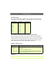
Installation Guide 6 System Requirements Before installing, you should be aware of the various requirements that will apply for your application, and in particular for the desired frame rate. The values shown below are obtained from real-life tests.
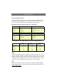
Installation Guide Hard Disk Space The amount of disk space required can be roughly calculated from the table below. Always add a further 5-10% disk space as a safety margin. Average File Size Stored Images Disk space (GB) 15 KB 60 000 1 15 KB 150 000 2.1 15 KB 600 000 9 25 KB 60 000 1.8 25 KB 150 000 3.9 25 KB 600 000 15 35 KB 60 000 2.1 35 KB 150 000 5.
Installation Guide 8 Installation Step 1 - Locate your License Code To install the full retail version of AXIS Camera Recorder a valid license code must be entered. This code can be found on the product label in the software retail box. The license code starts with “ACR” and is followed by a combination of letters and numbers. A license code is not required to install the Demo version of the program. Step 2 - Connect Devices Connect your Axis cameras/video servers to your Local Area Network.
Installation Guide If a demo version of AXIS Camera Recorder was already installed, it will be necessary to remove the image databases. This can be done either by uninstalling the demo version or by clearing each camera database from within the new version of the AXIS Camera Recorder software. See also Setting Image Quality and Recording Conditions, on page 18. Step 4 - Configure for First Use After installing the software, it must be configured for your cameras and/or video servers.
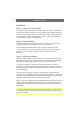
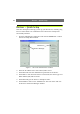
Devices - Quick Setup Devices - Quick Setup This short description will help you set up your first device, without going into too much detail. It is assumed that the software has already been successfully installed. 1. Start the Administrator application and click the Add Device… button. The Device Setup Wizard starts. Add Device Monitor Manager Figure 1 - The main Administrator window. 2. Enter the IP address of the Axis camera/video server. 3.
Devices - Quick Setup Now that a device has been added we will add the camera to the Monitor application and configure its layout. 1. Click the Monitor Manager button in the Administrator. Figure 2 - The Monitor Manager window. 2. Select a Layout Size (e.g. 2x2 = 4 cameras) and click on one of the monitor windows. The selected monitor window turns light grey. 3. Select a camera for the active monitor window. An image from that camera will be shown in the monitor window. 4.
Devices - Quick Setup 12 Using the Monitor application 1. Now open the Monitor application. You should now see the image from your camera. If not, the camera was not properly added to the Monitor manager. Go back to the previous page and add the camera again. 2. Click the Manual button. This enables the Start, Start All and Stop All buttons. 3. Click on the monitor window for the camera - this makes it the active monitor window. 4. Now press the Start button to start fetching images from the camera.
The Administrator Application The Administrator Application The Administrator application is used when setting up the system for the first time, when new cameras or video servers are added to the system, and whenever the system configuration needs to be changed. It is also used to configure the layout of the Monitor application, which recording conditions to use, etc. The Administrator is started from the Program Menu.
The Administrator Application • Add Device - Add new cameras or video servers. See the previous section Devices - Quick Setup, on page 10 and the more detailed section Changing Device Settings, on page 15. • Edit Device - Edit/update the configuration of an existing device. • Remove Device - Removes an existing device from the system. • Settings - Set up image quality and recording conditions, etc. for the camera. See Setting Image Quality and Recording Conditions, on page 18.
The Administrator Application MAC address (S/N) - This is the hardware address of the camera/video server, e.g. 00408c291ba2 and it corresponds to the serial number found on the product’s serial number label. This is the MAC address used to initially install the device. Name - The name for the camera/video server should reflect its usage or location. Note that two devices cannot use the same name. Camera Setup - Used to set up/modify camera names and PTZ devices for the device.
The Administrator Application Configuring Video Servers For video Servers, you must specify if the connected cameras are Pan/Tilt/Zoom cameras or not. You can also give names to individual cameras. To do this, select the video server in the device list and then click the Edit Device button. Then click the Camera Settings button to access the cameras connected to the server. • Check the box provided to indicate if any of the cameras connected to the video server are Pan/Tilt/Zoom cameras.
The Administrator Application Configuring Monitors and the Layout Once the software has been configured for your cameras and video servers, you should then set up the screen layout for the Monitor application, and specify where each camera should be displayed on the screen. Important! Adding a camera in the Monitor Manager is a required step to enable the display of the camera in the Monitor application. If a camera is not configured for display here, it will not appear in the Monitor application.
The Administrator Application 18 Hot Spot Window - This special window can be used for various purposes and will, when enabled, occupy up to 9 (3x3) of the available windows, depending on the layout in use. The Hot Spot window can show an enlarged view from one camera, it can be used for interactive PTZ control, or it can be used to browse through previously recorded images (Quick Browse). To use the function, select Hot Spot and the desired window layout.
The Administrator Application Save images within … - If Images with motion has been selected as the recording condition, it is then also possible save images from immediately before and after the alarm, i.e. when the detected motion exceeds the given limit. These images are constantly buffered for the selected period (e.g. 5 seconds before and after) and are thus always ready to be stored when the alarm occurs.
The Administrator Application 20 For all cameras combined, a maximum total of 160 GByte can be saved. Delete images older than - (in minutes, hours or days). Select this to limit the recordings in the database by age. When selected, images will automatically be deleted when older than the specified age. Note that it is not possible to store more than 600.000 images per camera, even if the maximum age is set as very high. Database Path - Specify the directory for the image database.
The Administrator Application Exclude Regions Settings It is also possible to set up regions for the camera that should be excluded from motion detection. Exclude Regions… - Click this button to specify the areas to exclude. See also Defining Motion Detection Exclude Areas, on page 24. Region Color… - Select a color for the excluded region. Image Quality… This activates the Configure Device dialog, where the camera image quality, including the image size and its compression, can be set up.
The Administrator Application 22 Calibrating Motion Detection The motion detection system can control (a) when images are saved to disk, and (b) when alarms are generated, and is therefore a vital element of the system. Motion detection requires careful calibration or it will not function properly. Follow the instructions below. It is recommended that any regions that should be excluded are from motion detection are configured before calibrating motion detection. See page 24.
The Administrator Application Noise Sensitivity Slider - Adjusts the noise sensitivity level of individual picture elements (pixels). The noise sensitivity level determines when the change in light intensity and color (light change) of individual pixels should be considered noise (i.e. an insignificant change) and when it should be considered motion (i.e. a significant change).
The Administrator Application Defining Motion Detection Exclude Areas Areas that should not be included in the motion detection area can be excluded from the image by marking the relevant areas in the Exclude Regions settings. Filled squares indicate that motion will not be detected here. Figure 6 - The Exclude Regions dialog. Clicking in the image with the left mouse button will exclude squares from the motion detection, as shown above, and clicking with the right button will include them.
The Administrator Application Setting Up and Using PTZ Preset Positions Up to 25 PTZ preset positions (PP’s) can be created for absolute positioning PTZ cameras. These are then accessible in the Monitor application’s control panel. For relative PTZ cameras, the number of PP’s will depend on the Axis video server and the PTZ driver used. For relative PTZ cameras, only the PP’s defined in the video server will be listed and available for use.
The Administrator Application Tilt (Vertical bar) - Click on the bar to set the tilt position for the camera. When clicking, the tilt level will be set to the level indicated by the cursor position on the bar. Pan (Horizontal bar) - Click on the bar to set the pan position for the camera. When clicking, the pan level will be set to the level indicated by the cursor position on the bar. Pan/Tilt buttons - Press the buttons in order to move the camera in the direction indicated by the button.
The Administrator Application General Settings The General Settings dialog box allows you to define various administrative settings, as described below. Figure 8 - The General Settings window. Logfile Path - Specify the directory on the disk where the log files should be located. The specified directory must already exist, as it will not be created automatically. Days to log - Specify the number of days to store the log files. A new log file will be created each day.
The Administrator Application 28 E-mail Setup The e-mail alerting system must be configured prior to use. The following settings must be configured; Enable E-mail - Select to enable E-mail alerting. Note that camera and system failures will automatically be sent via e-mail if this has not been disabled under Advanced in the General settings window. Advanced… - If a simple MAPI mail client is not available, SMTP e-mail can instead be used.
The Administrator Application Scheduling Camera Activity and Alert Periods Using a a one-week calendar, the built-in Scheduler provides automatic control over important system functions.
The Administrator Application E-mail - Check to enable (or delete) periods during which e-mail alerts will be sent for events for the selected camera. Before setting up e-mail alerts, e-mail must be configured in the General Settings dialog, also available from the main Administrator application. See E-mail Setup, on page 28. Sound - Check to add (or delete) sound alerts for events for the selected camera.
The Administrator Application 6. Click the day name again to zoom out. 7. You should now see a purple bar that represents the times you specified. This bar indicates that the selected camera will be active during this period. We now need to cover the rest of the week, but we now only want the camera to be triggered by events, i.e. when something out of the ordinary happens outside the working week. 8. Repeat steps 1 and 2 as above. 9. Drag the cursor to cover the period Sunday 00:00 to Monday 08:00. 10.
The Monitor Application 32 The Monitor Application The Monitor application is the heart of the AXIS Camera Recorder system, and is used for all normal day-to-day operation. Besides being the main user interface, the Monitor starts and stops the cameras, acquires and displays images, detects motion, saves images in the databases, sends alarms, etc. Important! The surveillance system will only be active when the Monitor application is running.
The Monitor Application When the Monitor application is started, it automatically starts any cameras that have been specified in the Scheduler as being Online at that time. The Scheduler can be disabled and overridden by pressing the Manual button, which allows all the cameras to be started manually, one at a time, by clicking the Start button for the selected camera, or alternatively, all at once, by clicking the Start All button.
The Monitor Application Buttons for manual control of outputs - These buttons are used to manually control any outputs that have been linked to the camera currently selected. The outputs controlled by these buttons can be on any device/camera in the system. To set up outputs, please see page 39. To link an output to a particular camera, please see page 21. Quick Browse (QB) - Switches between on-line mode and quick browsing mode in the Hot Spot window.
The Monitor Application 35 The Hot Spot window supports interactive Pan/Tilt/Zoom. When PTZ Mode is enabled, click in the Hot Spot window and hold down the mouse button while dragging. A slider (0-100%) indicating the zoom factor will appear. Move the slider to the desired zoom factor and release the mouse button. The camera will now center on the spot you pointed to and zoom with the factor you selected.
The Monitor Application Camera - Select the camera to view recordings from. Data/Time - Use these controls and press the Go To button to jump directly to the specified date and time. If no image was recorded for the specified time then the first recorded image found after the specified time will be shown. Note that when using times to view recordings, you can also select any other camera and view the recordings from that camera from the same time.
The Monitor Application 37 Features in Advanced Mode Advanced mode allows you to print or export individual images, create AVI video files and zoom into or out of the images. Clicking the Advanced button displays the following information and buttons: • Records - Shows the number of images currently stored for the selected camera. • Record Limit - Shows the maximum size of the image database for the selected camera.
The Monitor Application • Create AVI - Press this button to create an AVI file, using the images included in the period/region defined by start time to end time (see previous page.) Enter the name of the AVI file to create in the Create AVI dialog and optionally include a timestamp. Once the file has been named, Figure 15 - The Create AVI dialog. the dialog will ask for the compression codec to use.
Inputs and Outputs Appendix A - Inputs and Outputs Advanced Control with Input Devices Axis Network Cameras and Video Servers support the use of various types of input devices, for example, passive infrared sensors, or door and window contacts. Please refer to the device’s manual for a description of how to connect input devices. By using the device’s inputs, AXIS Camera Recorder allows you to control camera activity, to send e-mail alerts and to activate the device’s output ports.
Inputs and Outputs A plus sign (+) will now appear to the left of the device to which the sensor is connected. Click this to see the defined external event entry. The event name appears under the device, which indicates that this event is controlled through that device. We will now create a timer event, which is tied to the new external event; 1. Select the external event we created previously by clicking on it in the Defined Events window.
Inputs and Outputs 6. Now find the start time of the event-controlled period and click and drag the mouse to the end time. 7. You will now be asked to define the selected time period as On Events or Always. Select On Events and the selected time period turns yellow in the Scheduler overview. When online event periods have been set, click the OK button in the Camera/Alert Scheduler dialog box to start using the event settings and to return to the main window.
Inputs and Outputs 42 I/O Control Clicking on the I/O Control button brings up a group of panels from where it is possible to define which events will control which outputs. An event can control multiple outputs, and an output can be controlled by multiple events. Figure 17 - The I/O Control window. To attach an event to an output - select the event from the first panel, and then the output from the second. Then click the >> button to set the attachment.