v1.2 Closer to Real, USB2Dynamixel User’s Manual ROBOTIS CO.,LTD. www.robotis.
User’s Manual contents 1. Introduction··························· 2 1-1. 1-2. 1-3. 1-4. Functions································ Composition ······························ System Requirements ·························· USB2Dynamixel Connection ······················· 2 3 3 4 1-4-1. USB2Dynamixel Structure························· 4 1-4-2. Connection of AX series Dynamixel ···················· 5 1-4-3. Connection with DX/RX series Dynamixel ················· 6 1-4-4.
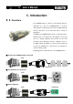
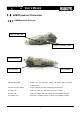
User’s Manual 1. Introduction 1-1. Functions The USB2Dynamixel is a device used to directly drive the dynamixel on a PC. The USB2Dynamixel is used by connecting to a USB port of a PC, and is equipped with 3p and 4p connectors to be connected with a variety of dynamixels. In addition, the USB2Dynamixel can be used to transform a USB port into a serial port for a PC without a serial port such as a lap-top computer.
User’s Manual 1-2. Composition ◎ USB2Dynamixel The USB2Dynamixel is used when a dynamixel is directly driven on a PC without a dynamixel exclusive controller such as the CM-2, CM-2+ and CM-5. It is also used to transform an USB port to a serial port. ◎ Software A software that can directly drive a dynamixel on a PC only with the USB2Dynamixel without a dynamixel exclusive controller such as CM2, CM-2+ and CM-5 is provided. There are two types of software provided: 1. USB2Dynamixel driver 2.
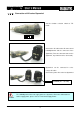
User’s Manual 1-4. USB2Dynamixel Connection 1-4-1.
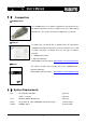
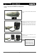
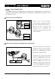
User’s Manual 1-4-2. Connection of AX series Dynamixel Set the function selection switch to TTL mode Connect the 3P cable to the 3P connector of USB2Dynamixel and the connector of the dynamixel (There are two connectors on the dynamixel, any of which can be connected). Dynamixels can be connected in series using a 3P cable. Connect the power line to the last dynamixel. POWER (DC 7 to 10V) The USB2Dynamixel does not supply power to a dynamixel.
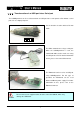
User’s Manual 1-4-3. Connection with DX/RX series Dynamixel Set the selection function switch to RS 485 mode Connect the 4P cable to the 4P connector of USB2Dynamixel and the connector of the dynamixel (There are two connectors on the dynamixel, any of which can be connected). Dynamixels can be connected in series using a 4P cable. Connect the power line to the last dynamixel.
User’s Manual 1-4-4. Transformation of an USB port into a Serial port The USB2Dynamixel can be used to transform an USB port into a serial port for a PC without a serial port such as a laptop computer. Set the function selection switch to RS 232 mode. The CM-5 communicates using a serial port. When the USB2Dynamixel is used, the network with CM-5 can be made even using an USB port of a PC.
User’s Manual 1-4-5. Pin Figure The following pictures show the usage of the connector pins used in the USB2Dynamixel. To make them suitable for the intended purpose, the user should only use them after being familiarized with the usage of each pin. Pin Figure of 4P/3P Cable Connector 4 Pin Cable Pin No. Signal 1 GND 2 NOT Connected 3 DATA + (RS-485) 4 DATA - (RS-485) 3 Pin Cable Pin Figure 4 3 2 1 Pin No.
User’s Manual 1-4-6. How to Supply Power The USB2Dynamixel does not supply power to a dynamixel. Thus, additional power is needed to drive a dynamixel as shown below. For proper voltage to be provided to each dynamixel model, please refer to the dynamixel manual. ◎ Power Connection to the Dynamixel Based PIN#1: - on the “1-4-5 Pin Figure”, connect the plus (+) power to the No. 2 pin of the connector, and the minus (-) PIN#2: + power to the No.
User’s Manual 1-5. Installation 1-5-1. Installation of Driver < Step 1 > Download the Dynamixel Driver file from our website and uncompress it. ( www.robotis.com/usb2dynamixel ) < Step 2 > Connect USB2Dynamixel to a PC, and the New Hardware Search window will apear on the PC. Click on [Install from the list or Specific Location]. < Step 3 > Move to where USB2Dynamixel driver folder which was uncompressed from step 1.
User’s Manual < Step 5 > Select Control Panel>> System>> Hardware>> Management Console. Check whether “USB Serial Port” is installed at “Port (COM and LPT) of the Management Console. It would be convenient for the user to remember the number of port (COM #) for network connection. < Step 7 > Double-click on “USB Serial Port(COM#)”, and select “Port Setting >> Advanced” to modify the Latency time to 1ms. Doing such will increase the network speed.
User’s Manual 1-5-2. Installation and Implementation of the Dynamixel Manager < Step 1 > Make a connection of PC-USB2Dynamixel-Dynamixel as shown below, and supply power to the dynamixel unit(s). For further information on how to supply power, please refer to Section 1-4-6 How to Supply Power. USB Power line If the USB2Dynamixel driver is not yet installed on the PC and if the USB2Dynamixel is connected to the PC, the following window appears.
User’s Manual < Step 5 > When the window searching the dynamixel appears, press the ‘Search’ button. If the ‘Search’ cannot be implemented, redo ‘Search’ after cheching the following: 1. Check whether the port is selected correctly. 2. Check whether the function selection switch of the USB2Dynamixel is located correctly. 3. Check the status of the connection between the USB2Dynamixel and the dynamixel and the status of power supply. 4.
User’s Manual If there is a problem on the connection of the USB2Dynamixel, an error message appears as below. If the OK button is pressed, the Dynamixel Manager is implemented as below. In this case, restart from the Step 4 referring to the Connection menu of the Dynamixel Manager after checking the connection between the USB2Dynamixel and the PC. If there is a problem on the connection between the USB2Dynamixel and the dynamixel, an error message appears as below.
User’s Manual 2. Dynamixel Manager The Dynamixel Manager is a utility that helps manipulate a dynamixel from a PC easily. It can also change variables such as the ID or the Baud rate of the dynamixel. 2-1. Connection The Connection tab is used to set the connection status between the PC and dynamixel. Open / Close Opens or closes the network port of the USB2Dynamixel. Search Searches a dynamixel connected to the USB2Dynamixel. Exit Ends the Dynamixel Manager.
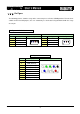
User’s Manual 2-2. List The List tab is used to show which dynamixel is connected to the USB2Dynamixel. The following picture shows that there are a total of three dynamixels connected. Specifically, two dynamixels with the Baud rate 1 are connected, and their IDs are No. 1 and 4. A dynamixel with the Baud rate 34 is connected, and its ID is No. 2. Only one dynamixel can be driven. To drive it, click on the corresponding ID.
User’s Manual 2-3. Operation The Operation tab is used to drive the dynamixels. Torque If ‘On’ is clicked, the output torque is applied to the dynamixel. If ‘Off’ is clicked, the output torque of the dynamixel is removed. LED If ‘On’ is clicked, the LED of the dynamixel is turned on. If ‘Off’ is clicked, the LED of the dynamixel is turned off. Speed Sets the driving rate of a dynamixel. Tune the rate by moving the scroll bar with the mouse.
User’s Manual the manual of each dynamixels. The Speed value 1 is the lowest speed, and the Speed value 0 the highest. Goal Position Sets the driving angle of a dynamixel. Adjust it by moving the scroll bar with the mouse. For the fine tuning, use the left and right direction keys ( ←, → ) on the keyboard. The value of Goal Position can be set 0 to 1023 as data value of position. The value in the brackets is the angle. The Center button is to move the dynamixel to the center (Position Data: 512).
User’s Manual Punch Sets the minimum value of output Torque. Torque Limit Sets the maximum value of output Torque. Status Displays the present status of a dynamixel. Status Packet Error Displays the nature of the error when an error occurs while a dynamixel is driving.
User’s Manual 2-4. Configure The Configure tab is used to set additional restrictive conditions necessary for driving a dynamixel. Save changed information by clicking on the Apply button after changing information. Operation Mode Selects a driving mode of a dynamixel. Joint: Used when the position/speed control is required like the joint of a robot. Wheel: Used when endless turn is required like a wheel. Angle Limit Sets a driving angle.
User’s Manual 2-5. Network The Network tab is used to set the functions necessary for the network of the dynamixel and the PC. Save information by pressing the Apply button after changing information. ID Sets the ID of a dynamixel. The ID connected to the USB2Dynaminxel is marked as [Occupied]. The ID cannot be changed using an Occupied ID. Baud Rate Sets the Baud rate between the dynamixel and the PC. It can only be changed to the main Baud rate.
User’s Manual 2-6. Information The Information tab displays information about the model and firmware version of the dynamixel connected at the moment.