
Installation manual


Application note Getting started with e100 AN00187-002
ABB Motion control products 14
www.abbmotion.com
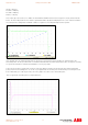
The peaks at the beginning and ends of the profile represent the acceleration and deceleration periods. The flat area in the centre is
the constant speed (steady state) section.
Increasing KPROP will reduce the magnitude of the peaks during acceleration and deceleration, however an excessive value is likely
to introduce oscillations in the overall response. KACCEL can be used as a means of reducing the following error during
acceleration and deceleration phases.
To fine-tune KPROP gradually increase its value, repeating the test move each time, using it to decrease the overall error and
improve the settling time of the axis at the end of the move. If KVPROP is too high it will be particularly apparent when the motor is
stationary as it will vibrate.
Other gain terms can be added to improve the response, but this is beyond the scope of this document. Please refer to the
manuals and help files for more information.
Connecting a
Connecting a Connecting a
Connecting a l
ll
load
oadoad
oad
When every part of the system has been tested and is working correctly it is time to connect the load. This will require some parts of
the servo system be re-commissioned. The MicroFlex e100 will need to re-measure the load inertia and this will require the speed
and position loop gains to be changed.
Using an appropriate accel and decel time is particularly beneficial when tuning loaded motors as a step response is very difficult to
achieve. Be very careful not to move too far or too fast during the test moves. It is always best to start with slow short moves and
increase until a reasonable motion profile is attained.
The value of KVELFF should not change, but the KPROP may need to be modified. Again make sure any test moves do not exceed
the limits of travel. Using scaled units may make this easier. Recalculate the scale factor to represent the mechanical system
connected to the motor, use units appropriate to the type of movement (mm for linear travel, degrees or revs for rotary travel).
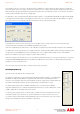
At this point it is a good idea to save the parameter file from the MicroFlex e100. Connect to the MicroFlex e100, select
Tools >
Parameter Table > Upload
, find a suitable folder on the PC and give the parameter file a name “Axis 3 Settings.ptx” for example.
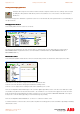
When commissioning the MicroFlex e100 is complete the drive needs to be switched back over to EPL as a Control Reference
Source. This is selected from the Tool bar as shown.
The drive commissioning is now complete. You have a choice of repeating the drive setup procedure again on a second drive or
moving on to setting up the NextMove e100.
It is assumed that two drives will be setup but one drive will be sufficient to complete the application note