
Installation manual


Application note Getting started with e100 AN00187-002
ABB Motion control products 19
www.abbmotion.com
Because the MicroFlex e100 is on an EPL network it is possible to read
and write many of the parameters in the drive every cycle of the EPL
network (every 2ms for the configuration we’ve made so far). There may
not be enough bandwidth to use them all. This depends on the cycle
time and the number of axes on the network. It is best to select only
those actually required.
This setup procedure will automatically map the essential drive attributes for control of a remote axis. You don’t need to add any but
in this example, we will, so that you know how it is done. There are two ways data can be passed:
Controlled Node <- Manager Node : this is data sent from the Nextmove to the drive
Manager Node -> Controlled Node : this is data sent from the drive to the Nextmove
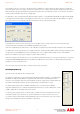
“AXISMODE” is an example of a useful keyword that we can map from the drive back to the Nextmove – e.g. so the Mint program
can use the value of this in the application (CURRENTMEAS and FOLERROR are other useful items). Double click or expand the
Process Data (Controlled Node->Manager Node tree and select Axismode in the tick box. As process data is mapped the PDO
Item count will start to grow towards its maximum limit.
TORQUELIMITPOS and TORQUELIMITNEG would be examples of items we might add as PDO mappings from the Nextmove to
the drive (e.g. to set torque limits in a tensioning or winding application).
The axis position is automatically mapped, but it is also possible to add a mapping
for encoder.
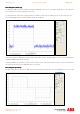
After clicking on Encoders->Encoder 0 on the Resource Mapping screen the dialog
to the right appears.
Map the MicroFlex e100’s encoder value to “Encoder 3” on the manager node (i.e.
the NextMove e100). This way everything about this drive is consistent (i.e. the
node address, axis number and encoder value are all set to 3). The encoder
resolution should always be set to 24 bits.
Once all these mappings have been completed, close the Resource Mapping
Dialogue and click Next.
The remote axis list reappears and now shows the remote e100 axis that we just configured. It is at this point that you can add
another axis if you have more than one MicroFlex e100. The procedure just outlined would then be repeated.
When all the axes have been configured click Next.