
Installation manual


Application note Getting started with e100 AN00187-002
ABB Motion control products 20
www.abbmotion.com
The dialog above shows two e100 axes added to EPL. Local axes (analog drives, steppers or virtual axes) can be added from this
dialog too. Local servo axes are not mapped over EPL. They use one of the NextMove e100’s Encoder inputs 0,1 or 2 and the
speed demand to the drive is sent via an analogue output (we might use an analog MicroFlex drive or an ACSM1 drive configured
for +/-10Vdc input as local analog axes for example). Click Next.
A summary screen follows this one. After the summary is the Configuration Complete screen. Here is a good opportunity to save
the .dcf (Device Configuration File). Click “Finish” to download to the controller. It is a good idea to include the option to reset the
controller after the download. This completes the configuration.
After the controller resets the bottom right hand LED on all the networked devices should light (and remain solidly lit rather than
flash). This indicates that the network has initialised correctly and that the device is an active member of the EPL network.
Performing test moves from the NextMove e100
Performing test moves from the NextMove e100Performing test moves from the NextMove e100
Performing test moves from the NextMove e100
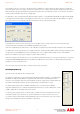
Check that all of the connections are correct and that the signals are working in the correct sense. Using Mint
WorkBench connected to the NextMove e100, select the Edit & Debug icon and type the following instructions at
the Command window. This is in the bottom right of the lower area of the Workbench screen, by default with a
black background. You need to click in this area first to move the focus to it before typing.
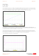
We are ready to try to move the motor, ensure there are no obstructions and that the motor is free to turn, either with the brake
released or with brake control setup on the drive so it releases when the drive is enabled.
If the motor moves out of control be ready to click the Enable icon on the WorkBench toolbar to disable the drive. Alternatively you
can push the stop button on the axis toolbar or operate the Emergency stop circuit if you have included this in your system design.
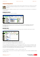
Setting scale factor.
Setting scale factor.Setting scale factor.
Setting scale factor.
To define motion in terms of useful user units it is normal to set a scale factor. The scale is calculated by determining the number of
encoder counts per user unit. Useful units may be motor revolutions (revs) or linear mm of travel for example. In this case our units
will be revs so we need to set the scale factor to suit the number of encoder counts per motor revolution.
SCALEFACTOR(3) = 10000
Stop button Enable / Disable button