
Installation manual


Application note Getting started with e100 AN00187-002
ABB Motion control products 9
www.abbmotion.com
The Position and Speed control loops are closed control loops which require feedback from the motor. A transducer fitted to the
motor generates a signal which is used to determine the actual position and speed of the motor. Any difference between this and
the demanded position and speed causes a demand on the current controller which in turn causes the motor to react to close the
gap. Each of these control loops has some associated gain terms, each of which require tuning to the system load conditions.
Before the tuning process can be started it is necessary to ensure that any brake fitted to the motor is released and an enable input
is provided to the MicroFlex e100.
If a brake is fitted to the motor make sure 24V is applied and check that the motor shaft is free to turn. Motor brake control is now
available locally on the MicroFlex e100 and MotiFlex e100 drives. See the section below entitled “Viewing and changing parameters”
for information on how to change the motor brake control parameters.
This application note is written under the assumption that the motor is being tested on a bench or at least under a light
load. If there is a load suspended vertically from the motor and the brake is disengaged while the drive is disabled then the
load will fall without any inhibition.
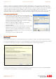
When setting up the MicroFlex e100 the drive has to be operated in Direct mode. This means that the “Control Reference Source” is
Workbench over USB rather than the NextMove e100 over EPL.
Select the “Control Reference Source” on the toolbar on the top of the page. In the popup box select “Direct (Host/Mint)”.
Workbench is the host in this case. If the drive was a MotiFlex e100 with a Mint option card then the drive would be Mint controlled
during operation. You would select the Control Ref as Direct in that case as well.
Autotuning
AutotuningAutotuning
Autotuning
To begin with it is always advisable to AutoTune the system with the motor disconnected from the load. This ensures that
the system is functioning correctly before moving the load and reduces the risk of causing damage. This application note
assumes the motor is unloaded and free to rotate in either direction.
If you are using a standard Baldor motor selected from the database and the wiring is correct, it should only be necessary to
complete the recommended Autotuning steps:- Calculate current loop gains, Measure the motor inertia, Calculate the speed and
position gains.