
User`s manual


AXIS M7014
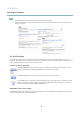
Hardware Overview
Hardware Overview
1
2
3
4
5
6
7
8
1.
Mounting holes
2.
Video input connectors
3.
LED indicators for power, status and network
4.
SD memory card slo t (microSD)
5.
RS-485/RS-422 connector
6.
Control button
7.
Power connector
8.
Nework connector (PoE)
Connectors
For technical specifi cations, see
page 44
.
Network connector - RJ-45 Ethernet connector. Supports P ower over Ethernet (PoE).
NOTICE
Due to local regulations or the environmental and electrical conditions in which the product is to be used, a shielded
network cable (STP) may be appropriate or required. Any network cab les that a re routed in ou tdoor environments or similar
shall be shielded (STP) and intended for their specific use. Make sure that the network switch is properly grounded. See
for regulatory requirements.
SD card slot - A standard or high-capacity SD card (not included) can be used for local recording with removable storage.
NOTICE
To prevent corruption of recordings, the SD card should be unmounted before removal. To unmount, go to Setup > System
Options > Storage > SD Card and click U
nmount.
Control button - The control button is used for:
• ConnectingtoanAXISVideoHostingSystemservice.See
page 32
. To connect, press and hold the button for about
1 second until the Sta
tus LED flashes green .
• ConnectingtoAX
IS Internet Dynamic DNS Service. See
page 33
. To connect, press and hold the button for
about 3 seconds.
• Resetting the product to factory default settings. See
page 39
.
Power connector - 2-pin terminal blo ck for power input.
RS-485/RS-422 connector - Two 2-pin terminal blocks for RS-485/RS-422 serial interface used to control a uxiliary equipment,
e.g. PTZ devices.
4