Installation guide
Manuals
Brands
Axis Manuals
Networking
P3367-VE
11
12
13
14
15
16
17
18
19
20
Page 14
AXIS P33-VE Seri
es Installation Guide
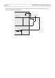
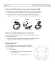
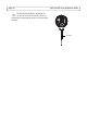
The following connection diagram gives an example
of how to connect an auxiliary device to the
AXIS P3346-VE/P3367-VE/P3384-VE.
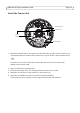
1
2
E.g. push button
3
4
3.3V
max. 50mA
D
S
G
1
...
...
12
13
14
15
16
...
...
26