
User`s manual


AXIS P7214 Video Encoder
Hardware Overview
Hardware Overview
2
3
4
1
IN 1 IN 2 OUT 1
1
2
3
4
5
6
7
8
9
10
11
12
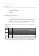
1.
Audio input 1
2.
Audio input 2
3.
Audio output 1
4.
Video input connectors
5.
LED indicators for po wer, status, network
6.
Mounting holes
7.
SD card slot (microS D)
8.
I/O connector
9.
RS-485/RS-422 connector
10.
Control button
11.
Power connector
12.
Network connector (PoE)
Connectors
For technical specifications, see
page 50
.
Network connector - RJ-45 Ethernet connector. Supports P ower over Ethernet (PoE).
NOTICE
Due to local reg u lations or the environmental a nd electrical conditions in which the product is to be use d, a shielded
network cable (STP) may be appropriate or required. Any netw ork cab les that are routed in ou tdoor environments or similar
shall be shielded (STP) and intended for their specific use. Make sure that the network switch is properly grounded. See
for regulatory requirements.
Audio in (pink) - 3.5 mm input for a mono microphone, or a line-in mono signal (left channel is used from a stereo signal).
Audio out (green) - 3.5 mm output for audio (line level) that can be connected to a public address (PA) system or an active s peaker
with a built-in amplifier. A stereo connector must be used for audio out.
SD card slot - A standard or high-capacity SD card (not included) can be used for local recording with removable storage.
N
OTICE
To prevent corruption of recordings, the SD card should be unmounted before removal. To unmount, go to Setup > System
Options > Storage > SD Card and click Unmount.
4