AXIS Q8414–LVS Network Camera Installation Guide
Legal Considerations Regulatory Information Video and audio surveillance can be regulated by laws that vary from country to country. Check the laws in your local region before using this product for surveillance purposes. This product includes one (1) H.264 decoder license and one (1) AAC decoder license. To purchase further licenses, contact your reseller. Europe Liability Every care has been taken in the preparation of this document.
The product shall be connected using a shielded network cable (STP) that is properly grounded. Japan この装置は、クラスB 情報技術装置です。この装置 は、家庭環境で使用することを目 的としています が、この装置がラジオやテレビジョン受信機に近 接して使用されると、 受信障害を引き起こすこと があります。 取扱説明書に従って正しい取り扱い をして下さい。 本製品は、シールドネットワーク ケーブル(STP)を使用して接続してください。また 適切に接地してください。 Korea 이 기기는 가정용(B급) 전자파적합기기로서 주로 가정에서 사용하는 것을 목적으로 하며, 모든 지 역에서 사용할 수 있습니다. 적절히 접지된 STP (shielded twisted pair) 케이블을 사용하여 제품 을 연결 하십시오.
AXIS Q8414–LVS Network Camera Safety Information Read through this Installation Guide carefully before installing the product. Keep the Installation Guide for future reference. Hazard Levels DANGER Indicates a hazardous situation which, if not avoided, will result in death or serious injury. WARNING Indicates a hazardous situation which, if not avoided, could result in death or serious injury. CAUTION Indicates a hazardous situation which, if not avoided, could result in minor or moderate injury.
AXIS Q8414–LVS Network Camera Safety Instructions NOTICE TICE NO • The Axis product shall be used in compliance with local laws and regulations. • Store the Axis product in a dry and ventilated environment. • Do not install the product on unstable brackets, surfaces or walls. • Use only applicable tools when installing the Axis product. Excessive force could cause damage to the product. • Use only accessories that comply with technical specification of the product.
AXIS Q8414–LVS Network Camera Maintenance NOTICE TICE NO • To clean the Axis product, use soapy water or other multi-purpose cleaning agents (acidic, alkaline, neutral)* and follow the instructions provided by the manufacturer. • If required, the Axis product can be cleaned with a water hose. Move the spray in a side-to-side motion. * Do not use abrasive cleaning products.
AXIS Q8414–LVS Network Camera Installation Guide This Installation Guide provides instructions for installing AXIS Q8414–LVS Network Camera on your network. For other aspects of using the product, see the User Manual available at www.axis.com Installation Steps 1. Make sure the package contents, tools and other materials necessary for the installation are in order. See page 9 . 2. Study the hardware overview. See page 10. 3. Study the specifications. See page 13. 4. Install the hardware. See page 15. 5.
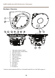
AXIS Q8414–LVS Network Camera Hardware Overview 1 2 3 4 5 6 7 8 9 10 12 1 2 3 4 5 6 7 8 9 10 11 12 13 11 13 Cable gasket (network cable) Cable gasket (I/O or audio cable) PoE Class selector * Network connector Audio out connector LED indicators Audio in connector I/O connector Control button IR window Microphone Not used SD card slot * Used for switching between PoE Class 2 (limited IR) and PoE Class 3 (full IR). See page 13.
AXIS Q8414–LVS Network Camera LED Indicators LED Color Indication Network Green Steady for connection to a 100 Mbit/s network. Flashes for network activity. Amber Steady for connection to a 10 Mbit/s network. Flashes for network activity. Unlit No network connection. Green Steady green for normal operation. Amber Steady during startup and when restoring settings. Red Slow flash for failed upgrade. Green Normal operation. Amber Flashes green/amber during firmware upgrade.
AXIS Q8414–LVS Network Camera I/O Connector Use with external devices in combination with, for example, tampering alarms, motion detection, event triggering, time lapse recording and alarm notifications. In addition to the 0 V DC reference point and power (DC output), the I/O connector provides the interface to: • • Digital output – For connecting external devices such as relays and LEDs.
AXIS Q8414–LVS Network Camera Specifications Operating Conditions The Axis product is intended for indoor use. Product Classification Temperature Humidity AXIS Q8414–LVS NEMA 250 Type 4X, IEC/EN 60529 IP66, Class 4M4 IEC 60721-3-4 0 °C to 50 °C (32 °F to 122 °F) 10-100% RH (condensing) Power Consumption NOTICE TICE NO Use a limited power source (LPS) with either a rated output power limited to ≤100 W or a rated output current limited to ≤5 A.
AXIS Q8414–LVS Network Camera DC output 2 Can be used to power auxiliary equipment. Note: This pin can only be used as power out. 3.3 V DC Max load = 50 mA Digital Input 3 Connect to pin 1 to activate, or leave floating (unconnected) to deactivate 0 to max 40 V DC Digital Output 4 Connected to pin 1 when activated, floating (unconnected) when deactivated. If used with an inductive load, e.g. a relay, a diode must be connected in parallel with the load, for protection against voltage transients.
AXIS Q8414–LVS Network Camera 1 Tip 2 Ring 3 Sleeve Audio Input Microphone/Line in Ground Audio Output Line out (mono) Ground SD Card Slot Supports SD cards with up to 64 GB of storage. For best recording performance, use an SDHC or SDXC card with speed class 10. Install the Hardware NOTICE TICE NO • The product shall be connected using a shielded network cable (STP). All cables connecting the product to the midspan shall be shielded (STP) and intended for their specific use.
AXIS Q8414–LVS Network Camera 70 mm (2.8 in) 100 mm (4 in) Install the Camera Unit 1. Remove the gaskets from the top- and side holes in the back chassis. 2. Position the back chassis in the corner between the ceiling and the walls. Use a pencil to make marks for the screws through the top- and side holes.
AXIS Q8414–LVS Network Camera 2 3 4 5 Cable gasket, I/O Screw (not included) Washer Gasket 3. Drill holes for the screws in the ceiling and in the walls. 4. Plug the gaskets back it into their holes. The gaskets should fit snugly with no folds or bends. 5. Remove the network cable gasket from the back hole and route the network cable through this back hole. 6. If applicable: Remove the I/O cable gasket from the back hole and route the I/O cable through this back hole. 7.
AXIS Q8414–LVS Network Camera 3 1 4 2 5 1 2 3 4 5 Cable gasket, network Cable gasket, I/O Screw (not included) Washer Gasket 12. For optimized sealing: Apply a strip of flexible gap filler / mastic sealant along the sides of the back chassis. Ensure that any gaps between the back chassis and the ceiling / walls are filled. 13. If applicable: Insert an SD card (not included) into the SD card slot on the camera assembly. 14.
AXIS Q8414–LVS Network Camera ±5° 19. Guide the network cable through the cable tunnel to the back of the camera assembly and plug the network cable into the network connector. 20. If applicable: Guide the I/O cable through the cable tunnel to the back of the camera assembly and plug the I/O cable into the I/O connector. 21. Hold the camera assembly so that the IR window on the front is in a six o’clock position, and place the bottom of the camera assembly against the bottom of the back chassis opening.
AXIS Q8414–LVS Network Camera 22. Fold the top of the camera assembly upwards until the camera assembly is pressed against the entire rim in the back chassis opening. Important Adjust the cable slack so that the cables are not squeezed between the sides of the camera assembly and the back chassis. 23. Attach the camera assembly to the back chassis using the screws (torque 2.5 Nm). 24. Remove the protective film on the front of the camera assembly.
AXIS Q8414–LVS Network Camera Maximum Tilt Positions for the Lens Your tilt position for optimal field of view is found in between the maximum tilt positions. Tilt up 45° 2.45 m (8 ft ) 0.7 m (2 ft 4 in ) Tilt down 45° 2.45 m (8 ft ) 1.8 m (6 ft ) 2.3 m (7 ft 4 in ) Install an SD Card It is optional to install a standard or high capacity SD card (not included), which can be used for local recording with removable storage. 1. Loosen the screws in the front and remove the camera assembly. 2.
AXIS Q8414–LVS Network Camera 4. Fold the top of the camera assembly upwards until the camera assembly is pressed against the entire rim in the back chassis opening. Important Adjust the cable slack so that the cables are not squeezed between the sides of the camera assembly and the back chassis. 5. Attach the camera assembly to the back chassis using the screws (torque 2.5 Nm). NOTICE TICE NO To prevent corruption of recordings, the SD card should be unmounted before it is ejected.
AXIS Q8414–LVS Network Camera Install AXIS Door Switch A for intrusion detection (sold separately) 1. On the back of the camera assembly: place the switch in the empty compartment next to the cable tunnel.
AXIS Q8414–LVS Network Camera 2. Attach the switch to the compartment using the screws. 3. Guide the I/O cable through the cable tunnel to the back of the camera assembly. 4. Snip off any excessive length from the I/O cable and fit the I/O connector block to the I/O cable. 5. Plug the I/O connector block into the I/O connector. Install AXIS Q8414-LVS Smoked Dome (sold separately) 1.
AXIS Q8414–LVS Network Camera 5. Replace the IR light window in the front opening with an IR light window from the kit. 6. Place the camera holder in its original position on the back of the camera assembly. Important Ensure that the IR light window is positioned in its compartment. 7. Tighten the black screws (T20, torque 2.5 Nm) to attach the camera holder to the camera assembly.
AXIS Q8414–LVS Network Camera Reset to Factory Default Settings Important Reset to factory default should be used with caution. A reset to factory default will reset all settings, including the IP address, to the factory default values. Note The installation and management software tools are available on the CD supplied with the product and from the support pages on www.axis.com/techsup To reset the product to the factory default settings: 1. Disconnect power from the product. 2.
Installation Guide AXIS Q8414–LVS Network Camera © Axis Communications AB, 2014 Ver. M1.12 Date: October 2014 Part No.