User’s Guide ENGLISH AXIS T8414 Installation Display
About this Document This document includes instructions for setting up and using the AXIS T8414 Installation Display. Legal Considerations Video and audio surveillance can be prohibited by laws that vary from country to country. Check the laws in your local region before using this product for surveillance purposes.
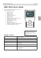
AXIS T8414 User’s Guide Page 3 AXIS T8414 User’s Guide This user’s guide provides instructions for using the AXIS T8414 Installation Display.
Page 4 AXIS T8414 User’s Guide Overview AXIS T8414 is a battery-powered, handheld device that greatly simplifies the installation of both Axis network cameras and analog cameras. It displays live video from a camera and makes setting a camera’s viewing angle and focus at the installation site easier than with the use of a laptop or remote computer. It offers user-friendly features such as touchscreen, zoom and snapshot functions.
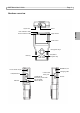
AXIS T8414 User’s Guide Page 5 Hardware overview Stylus slot AV in Data indicator LED Power indicator LED ENGLISH Light sensor LCD screen Navigation keys Start/Enter Snapshot key ESC key POWER on/off Power bank on/off LAN/PoE OUT USB slot CAT5 Cable tester port LAN/PSE IN (External power bank not included) Micro SD slot Charging LED DC12V
Page 6 AXIS T8414 User’s Guide Unit connectors LAN/PoE OUT - RJ-45 Ethernet connector. Provides power to network cameras that are PoE enabled. LAN/PSE IN - The Power bank provides 48 V DC power (External power bank not included). USB slot - Connect USB storage devices for data storage. Micro SD slot - Insert a Micro SD card into the slot for data storage. AV in - BNC connector for connecting an analog camera. Use a 75 ohm coaxial video cable. CAT5 Cable tester - for testing and detecting wiring types.
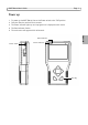
AXIS T8414 User’s Guide Page 7 Power up 1. 2. 3. 4. 5. To power up the AXIS T8414, first set the Power switch to the “ON” position. Press the Start key and hold for 3 seconds. The Power indicator lights up. and a progress bar is displayed on the screen. The Data Indicator flashes The main menu will appear within 45 seconds.
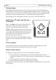
Page 8 AXIS T8414 User’s Guide Viewing images With AXIS T8414 Installation Display you can connect to a camera either through Connect or Device Search for viewing images, see Connect and Device Search, on page 11. The default view from the camera is at a relatively low resolution. When zooming into the view (see Digital zoom below) the camera's own default resolution is used instead, to provide greater detail. Press the ESC key on the AXIS T8414 front panel at any time to exit the viewing screen.
AXIS T8414 User’s Guide Page 9 Cameras with optical zoom For cameras that support optical zoom, this is controlled by the following: Press and hold the Up or Down navigation key for continuous optical zoom, in or out. Press and release the Up or Down navigation key for optical zoom in single steps, in or out. When digitally zoomed into the image, tap the ZF (Zoom/Focus) indicator/switch to switch to PT (Pan/Tilt) mode.
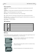
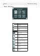
Page 10 AXIS T8414 User’s Guide Menus - Main menu Button Function Main Menu. Return, go to previous page. Enter, opens a submenu or saves settings. PoE indicator Battery status Connect to an Axis network camera.
AXIS T8414 User’s Guide Page 11 IP Camera Connect Connect a network cable from the camera’s network port to one of LAN ports on the AXIS T8414. In the Main menu tap IP camera and Connect. Waiting will appear on the LCD display. When the camera is connected successfully, its image will display in the screen. Device Search Device search can be used to find all cameras in a local network or a single camera directly.
Page 12 AXIS T8414 User’s Guide AV In Video in Test analog video by connecting the BNC cable from the camera's video output to the AXIS T8414 video input port. Tap the AV In icon in the Main Menu, and the video signal will be displayed on the LCD screen. Press the ESC key to return to the menu. To adjust the contrast in the image, go to Setup > Setup AV. Network cable test Follow these steps to test a network cable for type; straight or cross, and for errors; open, short or miswire. 1.
AXIS T8414 User’s Guide Page 13 Power over Ethernet AXIS T8414 delivers PoE to Axis network video products with PoE support either from the unit's battery or from PoE by-pass. Tap this icon to turn on and off Power over Ethernet. PoE Setup Power Level The output Power Consumption Level range can be set according to different needs. The options include , , and Mid-High (6~25W+EXT 12V)>.
Page 14 PoE Measurement Display Select the desired combination of PoE Measurement information from the drop-down list, including Voltage (V), Current (I), and Power Consumption (P). Enable PoE after Tester Bootup To enable PoE while the Tester is booting up, please select from the drop-down list of . The Tester will provide power to the camera right after system startup. PoE Auto-shutdown Set the PoE auto-shutdown interval to 20 seconds, 40 seconds or 60 seconds.
AXIS T8414 User’s Guide Page 15 SETUP Under SETUP are the menus for IP, AV, System, and Snapshot ENGLISH Setup - IP Setup - IP connection These settings are optional and advanced. In most situations the you will not need to change them. The settings that cannot be changed are intended for future use. Leave other settings as they are, unless specifically required. 1. Tap the Setup- IP connection icon. Enter the information in each field using the stylus.
Page 16 AXIS T8414 User’s Guide Camera Type- AXIS Camera (by default) User Name - enter the user name for the camera. By default Axis’ products have “root” Password - enter the password for the camera. By default Axis’ products use “pass”. To reveal the password being entered, tap Show. Management Port, Streaming Port, Streaming Format, and Streaming Protocol can be left at their default settings unless the camera has been set up with different settings. 2.
AXIS T8414 User’s Guide Page 17 Snapshot Function Snapshot key Edit Once the Snapshot key is pressed, the Snapshot editing page will open. Choose a location to store the snapshot by tapping on T8414, USB or SD. 1. Enter a file name and description. 2. Tap Enter/Save icon and return to the viewing page. File management To manage snapshot files from the Main Menu tap the SETUP icon > Setup-Snapshot. Here you can preview, copy and delete images. 1.
Page 18 AXIS T8414 User’s Guide Video Recording The Tester supports Video Recording, Video Setup, Video File Management and Video Playback function for camera live views when necessary. Implement Video Recording In the camera’s live view mode, tap the text “REC” on the right top corner of the live view screen to start Video Recording. During the recording process, the text will be in red. Tap the text “REC” one more time to stop Video Recording.
AXIS T8414 User’s Guide Page 19 Assign a storage location (Tester/ USB/ SD) located on the top of the setup page and save the videos by tapping the radio button to the left side of the selected option. Enter the file name and description for the snapshot. Tap to save all the settings and return to the live view mode, or tap to exit the setting page without saving settings. Preview, copy and delete video on the page.
Page 20 AXIS T8414 User’s Guide All Files Copy Tap the
AXIS T8414 User’s Guide Page 21 Auto Shutdown - To save power, tap the drop-down list to choose the amount of idle time before AXIS T8414 shuts down. Alternative connection methods External powerbank Connect a camera to PoE out, connect a powerbank to PSE IN, set the Powerbank’s switch to the ON position.
Page 22 AXIS T8414 User’s Guide Technical Specifications Function/ group Item Specification Model AXIS T8414 Installation Display Color LCD Field Display 3.5 inches Resolutions 320x240 Video Image settings Autosensing Network IP Setting • Static IP address • DHCP General Casing ABS plastic Memory 128 MB RAM (16 MB available for snapshots) Power • 12 V DC +/- 10%, 1 A • CANON BP-915 (7.4 V 2000 mAh) 80% capacity after 300 charge cycles Charge time 3.
User’s Guide AXIS T8414 © Axis Communications AB, 2012 Ver.1.00 Printed: January 2012 Part No.