AXIS T90B15 W-LED AXIS T90B25 W-LED AXIS T90B35 W-LED AXIS T90B20 IR-LED AXIS T90B30 IR-LED AXIS T90B40 IR-LED Installation Guide ENGLISH AXIS T90B Series
Legal Considerations Video and audio surveillance can be regulated by laws that vary from country to country. Check the laws in your local region before using this product for surveillance purposes. Liability Every care has been taken in the preparation of this document. Please inform your local Axis office of any inaccuracies or omissions.
Australia/New Zealand This digital equipment fulfills the requirements for RF emission according to the Class B limit of AS/NZS CISPR 22. The product shall be connected using a shielded network cable (STP) that is properly grounded. Korea 이 기기는 가정용(B급) 전자파적합기기로서 주로 가정에서 사용하는 것을 목적으로 하며, 모든 지역에서 사용할 수 있습니다. 적절히 접지된 STP (shielded twisted pair) 케이블을 사용하여 제품을 연결 하십시오. Safety Photobiological Safety This product fulfills the requirements for photobiological safety according to IEC/EN 62471 (risk group 2).
AXIS T90B Series Safety Information Read through this Installation Guide carefully before installing the product. Keep the Installation Guide for future reference. Hazard Levels Indicates a hazardous situation which, if not avoided, will result in death or serious injury. WARNING Indicates a hazardous situation which, if not avoided, could result in death or serious injury. CAUTION Indicates a hazardous situation which, if not avoided, could result in minor or moderate injury.
AXIS T90B Series Safety Instructions WARNING • The Axis product shall be installed by a trained professional. NOTICE TICE NO • The Axis product shall be used in compliance with local laws and regulations. • Store the Axis product in a dry and ventilated environment. • Avoid exposing the Axis product to shocks or heavy pressure. • Do not install the product on unstable brackets, surfaces or walls. • Use only applicable tools when installing the Axis product.
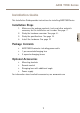
AXIS T90B Series Installation Guide This Installation Guide provides instructions for installing AXIS T90B Series. Installation Steps 1. Package Contents • • • AXIS T90B Illuminator including power cable 1 pre-mounted diverging lens 2 separate diverging lenses Optional Accessories • Mounting brackets • Remote control • Diverging lens with additional angle • Power supply For information about available accessories, see www.axis.com 7 ENGLISH 2. 3. 4.
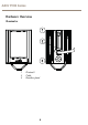
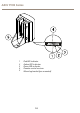
AXIS T90B Series Hardware Overview Illuminator 1 2 3 1 2 3 Photocell Cable Breather gland 8
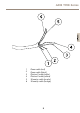
AXIS T90B Series 6 5 ENGLISH 4 3 1 1 2 3 4 5 6 Power cable (red) Power cable (black) Photocell cable (white) Photocell cable (yellow) Telemetry cable (purple) Telemetry cable (orange) 9 2
AXIS T90B Series 4 5 1 1 2 3 4 5 Red LED indicator Amber LED indicator Green LED indicator Remote control receiver Mounting bracket (pre-mounted) 10 2 3
AXIS T90B Series AXIS T90B40 IR-LED 3 ENGLISH 1 2 1 2 3 Cables Mounting bracket (pre-mounted) Bolt Optional Accessories Remote Control For information how to use the remote control, see Access the Product.
AXIS T90B Series 2 1 3 4 9 5 8 6 7 1 2 3 4 5 6 7 8 9 POWER ADJUST buttons PHOTOCELL ADJUST buttons TIMER buttons Photocell disable button DIM button RESET button STATUS button Disable remote control setup button TELEMETRY button Mounting Brackets To install the product using a compatible bracket from AXIS T90B Mounting Accessories, see the Installation Guide delivered separately with the mounting bracket.
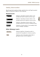
AXIS T90B Series LED Indicators There are three colored LED indicators on the base of the illuminator which provide operating and status information.
AXIS T90B Series Normal Operating Mode (Continued) Solid Amber Input voltage level error* Solid Red Internal LED error *Once the voltage error has been corrected, disable the remote control setup or restart the illuminator to turn the status LED off. Connectors and Buttons For specifications and operating conditions, see page 14.
AXIS T90B Series AXIS T90B25 W-LED 12–24 V AC/DC, max 48 W AXIS T90B30 IR-LED 12–24 V AC/DC, max 24 W AXIS T90B35 W-LED 12–24 V AC/DC, max 48 W AXIS T90B40 IR-LED 12–24 V AC/DC, max 96 W Install the Hardware To install the product using a compatible bracket from AXIS T90B Mounting Accessories, see the Installation Guide delivered separately with the mounting bracket. 1.
AXIS T90B Series CAUTION IR emitted from this product. Avoid prolonged eye exposure or use appropriate shielding or eye protection at distances of less than 1.5 m. Follow these installation procedures: 1. 2. If required, remove the screws and move the standard bracket to the top of the illuminator. If required, loosen the screws and turn the bracket 90°.
AXIS T90B Series ENGLISH 3. If required, loosen the screws and change to a diverging lens with the desired angle of illumination. The angle of illumination should be adjusted according to the camera field of view to light the whole scene adequately. See Technical Specifications.
AXIS T90B Series 2 1 1 2 Screws Diverging lens Note Adjust the vertical position of the illuminator to ensure that the field of view of the camera is illuminated.
AXIS T90B Series 4. Position the illuminator adjacent to the camera and point the illuminator towards the scene. ENGLISH CAUTION Red cable = +ve, Black cable = -ve (polarity sensitive) 5. 6. Mount the power supply. Connect the illuminator to the power supply.
AXIS T90B Series 1 3 2 1 2 3 7. Illuminator Power cable Power supply Set photocell following output (White & Yellow) Volt free output — normally open (day) to normally closed (night). Connect direct to camera if required to control switchover of day/night cameras. Access the Product Programming Mode The illuminator has the following default settings: • • • Power set to maximum 100% Photocell set to medium sensitivity level: 10 lux On, 30 lux Off.
AXIS T90B Series • • • • • Telemetry TEL enabled Telemetry input wires soldered together for automatic photocell operation Telemetry DIM disabled LED status indicators enabled Programming Mode Note The illuminator automatically switches from Programming Mode to Normal Operating Mode after 4 weeks. To switch to Programming Mode, restart the illuminator. 1. 2. 3. 4. 5. 6. Adjust the power, see Power Adjust on page 22. Adjust the photocell sensitivity, see Photocell Sensitivity on page 22.
AXIS T90B Series Power Adjust The power output of the illuminator can be adjusted between five pre-set levels. Select the required light intensity by using the buttons below. 5 4 3 2 1 1 2 3 4 5 20% of maximum 40% of maximum 60% of maximum 80% of maximum 100% of maximum Photocell Sensitivity Note When the photocell is disabled the illuminator will turn on and off from a telemetry input, regardless of ambient lighting conditions.
AXIS T90B Series There are three pre-defined levels to set the lux level threshold at which the photocell turns the illuminator on or off. Select the required sensitivity level by using the buttons below.
AXIS T90B Series Volt-free input: Non polarity sensitive Short circuit = Light on TTL input: Orange = TTL +ve Purple = TTL -ve (GND) 0 V = Light on 3 V = Light off The telemetry input wires (orange and purple) are soldered together when shipped from the factory to simulate a volt-free input so that the illuminator automatically turns on and off via the photocell. Any remote input or switch should be connected to these wires.
AXIS T90B Series 1. 2. 3. Turn the light on (night) and off (day) automatically via the photocell. This is the standard factory setting, no further action is required. Turn the light on and off from a remote switch or input. Used in conjunction with the Timer Function to turn the light on for a pre-defined period of time. When the DIM function is selected, a telemetry input into the illuminator will vary the brightness up and down.
AXIS T90B Series If you wish to cancel the timer period and have the illuminator operate under standard telemetry conditions, press Timer Disabled. 5 4 3 2 1 6 1 2 3 4 5 6 Timer disabled 1 minute 3 minutes 10 minutes 30 minutes TEL button LED Status Indicators This status indicator function can be switched on and off by pressing the STATUS button. This is the only button that has two states.
AXIS T90B Series Factory Default Note To activate this feature the button must be pressed continuously for 4 seconds. This is to avoid the possibility of activating this feature accidentally. Disable Remote Control Setup Note To enable Programming Mode after remote setup has been disabled, the illuminator must be powered off for at least 10 seconds. When turned on, the illuminator automatically re-enters Programming Mode.
AXIS T90B Series • Basics - • Check the LED status indicator. See LED Indicators. Check polarity of lamp connection: red = +ve, black = -ve Ensure power is 12-24 V AC or DC Ensure telemetry wires are shorted out or closed contact input (zero volt) is applied Check photocell is working. Cover photocell fully, light should turn on. It is sometimes difficult to see Infra-Red lamps working in high brightness conditions. Make sure that the power cable is within the specified distance.
AXIS T90B Series • Technical Specifications Models AXIS T90B15 W-LED AXIS T90B25 W-LED AXIS T90B35 W-LED AXIS T90B20 IR-LED AXIS T90B30 IR-LED AXIS T90B40 IR-LED Supported cameras IR-LED: All Axis cameras with IR cut filter W-LED: All Axis network cameras 29 ENGLISH Remote Control (optional accessory) Press the STATUS button to check the status of the remote control, see LED Status Indicators. Programming may be disabled.
AXIS T90B Series Power Input Voltage: 12-24 V AC/DC AC Frequenzy: 50-60 Hz Cable length 2.5 m (8 ft) Power Consumption maximum light / 20% of maximum light / Standby mode: AXIS T90B15 W-LED: 12 W / 3 W / 0.15 W AXIS T90B25 W-LED: 24 W / 6 W / 0.15 W AXIS T90B35 W-LED: 48 W / 12 W / 0.15 W AXIS T90B20 IR-LED: 24 W / 6 W / 0.15 W AXIS T90B30 IR-LED: 24 W / 12 W / 0.15 W AXIS T90B40 IR-LED: 96 W / 24 W / 0.
AXIS T90B Series Distance AXIS T90B20 IR-LED 10°x10° - 120 m (394 ft)* 35°x10° - 65 m (213 ft) 60°x25° - 45 m (148 ft) 80°x30° - 30 m (98 ft) 120°x50° - 20 m (66 ft)** AXIS T90B40 IR-LED 10°x10° - 310 m (1010 ft)* 35°x10° - 170 m (551 ft) 60°x25° - 112 m (367 ft) 80°x30° - 70 m (230 ft) 120°x50° - 65 m (213 ft)** AXIS T90B15 W-LED 10°x10° - 50 m (164 ft)* 35°x10° - 35 m (115 ft) 60°x25° - 20 m (66 ft) 80°x30° - 15 m (49 ft) 120°x50° - 10 m (33 ft)** AXIS T90B25 W-LED 10°x10° - 90 m (295 ft)* 35°x10° - 55
AXIS T90B Series 80°x30° - 30 m (98 ft) 120°x50° - 20 m (66 ft)** *No diverging lens **Optional accessory Casing Material: Polycarbonate IR-LED: Black W-LED: White and silver Display and indicators LED indicators Environment Outdoor Mounting Wall Ceiling Column Camera housing Approvals EN 55022 Class B, EN 55024 EN 61547, EN 55015, EN 50130–4 C-tick AS/NZS CISPR 22 Class B FCC Part 15 Subpart B Class B ICES–003 Class B KCC KN22 Class B, KN24 IEC/EN 60598–1 IEC/EN 62471 Risk group 2* IEC/EN 60529 I
AXIS T90B Series The size of the product shall be maximum (WxHxL): AXIS T90B15 W-LED: 75 x 100 x 64 mm (3 x 4 x 2.5 in) AXIS T90B25 W-LED: 100 x 135 x 66 mm (4 x 5 x 2.5 in) AXIS T90B35 W-LED: 135 x 180 x 68,2 mm (5 x 7 x3.2 in) AXIS T90B20 IR-LED: 100 x 135 x 66 mm (4 x 5 x 2.5 in) AXIS T90B30 IR-LED: 135 x 180 x 68,2 mm (5 x 7 x3.2 in) AXIS T90B40 IR-LED: 279 x 223 x 68 mm (11 x 9 x 3 in) Weight AXIS T90B15 W-LED: 600 g (1.3 lbs) AXIS T90B25 W-LED: 950 g (2.1 lbs) AXIS T90B35 W-LED: 1650 g (3.
AXIS T90B Series Warranty Information For information about Axis’ product warranty and thereto related information, see www.axis.
Installation Guide AXIS T90B Series © Axis Communications AB, 2014 Ver. M1.11 Date: May 2014 Part No.