Installation and Operating Guide Photovoltaik Module Production Series AC
Installation and Operating Guide INDEX 1 GENERAL RULES AND SAFETY PRECAUTIONS ........................................................... 3 2 INSTALLATION ASSEMBLY RULES ................................................................................... 4 2.1 Assembly Notes ......................................................................................................................................... 4 2.2 Assembly Variants ..................................................................
Installation and Operating Guide 1 General Rules and Safety Precautions The glass surfaces must not be damaged or scratched. In particular, the rear of the module must not be exposed to mechanical impacts (e.g. by sharp, hard objects). Do not stand on the modules or module frames. The solar modules must not be installed under bending tension and the frame parts must not be twisted in themselves during assembly. The solar module must not be compressed along its sides.
Installation and Operating Guide 2 2.1 Installation Assembly Rules Assembly Notes Modules must be handled with care during installation. Impacts to the front and rear or the edges can damage the modules. For a roof assembly, ensure that the structural dimensions (consult a structural engineer, if applicable) of the roof are adequate for bearing the loads imposed by the photovoltaic system. We recommend positioning the solar modules at an angle of at least 10° to a maximum of 75° to the ground.
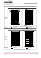
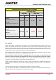
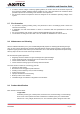
Installation and Operating Guide 2.2 Assembly Variants Installation with clamps, long side Installation with clamps, short side Sb S L Lb Mounting method: 60/72ce 120/144ce halfcut L S Comment Clamping area Substructure Clamping area Substructure Installation with inlay system, long side Installation with inlay system, short side Mounting method: 60/72ce 120/144ce halfcut Comment Substructure Substructure Al l drawings a re schematic diagrams and do not match reality.
Installation and Operating Guide Installation with mounting rails (clamps) Clamping range long side short side L (mm) Lb (mm) S (mm) Sb (mm) 250 - 450 100 35 - 300 265 60 cells Cell geometry 6 x 10 cells 120 cells Cell geometry 6 x 20 halfcut cells Loading capacity 5400 Pa 2400 Pa 72 cells Cell geometry 6 x 12 cells 300 - 500 100 forbidden forbidden 144 cells Cell geometry 6 x 24 halfcut cells Loading capacity 2400 Pa 0 Pa 2.
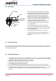
Installation and Operating Guide 2.4 Grounding Serrated washer Cable Ring terminal Washer Spring washer Module frame Proper earthing is the responsibility of the company carrying out the installation and is to be attached to the module frame. If a lightning protection system is already present or intended to be installed on the building, the PV system is to be integrated into the protection concept against direct lightning strike.
Installation and Operating Guide 2.7 Fire Protection 2.8 In order to reduce voltages caused by lightning strikes, the surface area of all conductor loops must be as small as possible. Modules shall be installed in such a way that sufficient air circulation will be possible to prevent an overheating of the modules and components. All connected electrical components must be designed for the maximum operating voltage of the system.
Installation and Operating Guide - 2x serial number/barcode: Each module has a unique serial number encoding, among other details, the year and month of manufacture. One serial number label is permanently fitted on the front below the glass and the second on the rear below the type label. It is not permitted to remove or cover labels. Removing or covering the labels will void the AXITEC warranty. 2.10 Notes AXITEC Energy GmbH & Co.
Installation and Operating Guide 4 CE/EG Declaration of conformity EN191204 10 / 10