Axium AX-400DA Multi-Zone Digital Amplifier Instruction Manual
Important Safety Instructions 1 2 3 4 5 6 7 8 9 10 11 12 13 14 Read these instructions. Keep these instructions Heed all warnings Follow all instructions Do not use this apparatus near water Clean only with dry cloth Do not block any ventilation openings, Install in accordance with the manufacturer’s instructions Ensure that the ventilation is not impeded by covering the ventilation openings with items such as newspapers, table cloths, curtains, etc.
Precautions 1. AC Fuse - The AC fuse inside the unit is not userserviceable. If you cannot turn on the unit, contact the dealer from whom you purchased this unit. 2. Care - Occasionally you should dust the unit all over with a soft cloth. For stubborn stains, use a soft cloth dampened with a weak solution of mild detergent and water. Dry the unit immediately afterwards with a clean cloth.
DECLARATION OF CONFORMITY We declare under our sole responsibility that this product, to which this declaration relates, is in conformity with the following standards: EN60065, EN55013, EN55020, EN61000-3-2 and EN61000-3-3. Following the provisions of Low Voltage Directive 2006/95/EC and EMC Directive 2004/108/EC, the EC regulation 1275/2008 and its frame work Directive 2009/125/EC for Energy-related Products (ErP). A NOTE ABOUT RECYCLING: This product’s packaging materials are recyclable and can be reused.
Supplied Accessories Table of Contents Make sure you have the following accessories: Important Safety Instructions Precautions Declaration of Conformity Supplied Accessories Features Front Panel Guide Rear Panel Guide Typical System Configuration Multiple Amplifier Stacks Controller Termination WEB Application Axium Music Centre Program RS232 Protocol Specifications VDE CEE 7/7 European Plug Schuko to IEC60320 C13 socket AS3112 Australasian Plug to IEC60320 C13 Socket Axium CD 5 2 3 4 5 6 8 9 10 12
Features Thank you for purchasing an Axium AX-400DA Multi-Zone Amplifier. Please read this manual thoroughly before making connections and plugging in the unit. Following the instructions in this manual will enable you to obtain optimum performance and listening enjoyment from your new Multi-Zone Amplifier. Please retain this manual for future reference. Multi-Zone, Multi-Source, Video Switching The 400DA amplifier has four separate amplifiers providing 4 zones of independent yet integrated control.
Presets and Paging Amplifier ON Status – “Amp-On” There are 14 amplifier presets and two page presets. Presets 1 - 14 are momentary and cause the amplifier to go to a predetermined setup, i.e. standby, volume & source selection. The presets may also be programmed with event scheduling, and are used by the alarm clock. The ‘Page Preset’ mode is for paging applications and is invoked by a contact closure between the 0V and PG1 or PG2 terminals. The contact closure must have an external power source i.e.
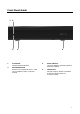
Front Panel Guide 1 2 3 4 1 Front Panel Solid Aluminium front Panel 2 Infra-Red Receiver Receiver for front panel IR control – Used only for amplifier control, not IR pass through. 4 3 Power Indicator The power indicator glows blue whenever AC power is applied. 4 Chassis Feet Set high enough to provide unrestricted air-flow through the chassis for convection cooling.
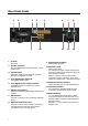
Rear Panel Guide 1 2 3 9 4 5 10 1 AC Inlet IEC socket 2 Speaker Terminals Plug in terminal clamp connectors accept 1.5mm² speaker wires 3 Expansion Bus RJ45 patch cable connects between expansion bus ports of amplifiers in a stack. 4 Coax Digital Input Terminals Coax digital (SPDIF) inputs. 5 Coax Digital Source Output Terminals Coax digital outputs for expansion to further amplifier zones. 6 USB for programming USB mini B socket for programming and firmware updates.
Typical System Configuration Zone 1 Gym AX-KPD Zone 2 Study AX-KPC Zone 4 Lounge TABLET To Ethernet router CD PLAYER Speakers in Zone 3 - not shown R SATELLITE RECEIVER TUNER DVD PLAYER FIG 1 10
Typical System Configuration – Continued FIG 1 depicts a typical configuration where the 400DA amplifier is providing audio into three of the possible four listening zones. Each zone consists of a room with a pair of speakers and a suitable controller. Each zone may be listening to any of the connected sources: Satellite, DVD, Tuner, Internet Radio, Media server, CD etc. Controllers Source Equipment Each zone has a specific control requirement. Choose controllers that best suit the application.
Multiple Amplifier Stacks To Next AX-400DA or AX-800DAV Multi-Zone Amplifier CD PLAYER SATELLITE RECEIVER TUNER DVD PLAYER FIG 2 In large installations where multiple 400DA or 800DAV amplifiers are required, the expansion bus may be used to convey inter-amplifier control, and common IR control. The source equipment audio must be plugged into the first amplifier where they are buffered and sent to the next amplifier in the stack. The maximum recommended expansion is eight units.
Controller Termination The 400DA is packed with control options: • • • • • • • • USB: Intended for initial installation Programming or firmware update. Not intended for permanent connection to a PC or other control system. ETHERNET: 100BaseT connection to a Home network router or switch. RS232 Serial: Electrically isolated Prevents hum in analog input circuits. CONTROLLERS: Conveys +12VDC, IR and Data between the 400DA and Axium keypad controllers, connected using CAT5 cables.
WEB Application The Axium 400DA amplifier has a WEB application which may be used for control and monitoring of amplifier and source functions. Home Page The home page provides access to the Amplifier zones. Selecting a Zone opens its control page.
Zone Control Page The Zone Control Page provides status & control of: • Standby • Volume: Slider or Up/Down button with readout. • Source Selection: S1 – S6 • Mute If the button is blue it indicates selection or ON status. Because of Web browser limitations, Slider setting changes are made using a positional touch on the slider The ‘Zones’ button is the Home Page return. Selecting the ‘Settings’ button will open the Settings page.
Zone Settings Page The Zone Settings Page provides status & control of: • Bass: Slider or Up/Down button • Treble: Slider or Up/Down button • Loudness • Balance: Slider or Left / Right button • Maximum Volume Limit: Slider or Up/Down button There is information displayed about the connected amplifiers Model and Unit ID and current Firmware version. The amplifier heatsink temperature is also displayed. The Back arrow button returns to the Zone Control Page.
Axium Music Centre Program AMC is an amplifier setup program, full control and tracking of the Axium amplifier zone is provided. The program runs on PC’s running Win XP, Win 7 or VISTA operating systems, and communicates via RS232, USB or Ethernet. AMC’s main window provides user functionality for real-time access and control of any amplifier zone. When an Axium amplifier is first attached to a PC running AMC the amplifiers clock is automatically set to the PC’s current time, date and location.
The Setup button opens the Setup window. Provides adjustments for Zone Equalisation, Balance, Delay, and Zone linking assignment. The Analog source input levels can be adjusted. If the source is a DVD player, the level should be set to 0dB. A Source will pulse red if input clipping is detected. Nominally the input should be set to 6dB. The Preset Setup on the AMC main page opens the Preset window. Preset programming can be entered for the Presets.
RS232 Protocol The RS232 serial port provides data acquisition and control of the Axium amplifiers by a home automation system, or PC. The interconnecting cable must be ‘Null modem’: 9 pin female ‘D’ connectors at both ends (pin connections 2 and 3 swapped at one end) only RX, TX & 0V (pin 5) are used. Baud Rate = 9600, Characters are all ASCII. Command Structure: line feed.
Data Command Standby (01) Mute (02) Source Selection (03) Volume (04) Bass (05) Treble (06) Balance (07) Send all parameters (09) Amplifier features (0C) Maximum Volume Limit (0D) Link Zone (0F) Volume Up (11) Volume Down (12) Zone Name (1C) Preamplifier Volume Mode (1D) Content 00 – Standby OFF 01 – Standby ON 04 – Toggle 00 – Mute 01 – Un-mute 02 – Toggle Mute 00 – S5 01 – S6 02 – S7 03 – S4 04 – S8 05 – S1 06 – S2 07 – S3 08 09 10 11 12 13 14 40 – S5 Audio only 41 – S6 Audio only 42 – S7 Audio only 43
Command Preset Selection (1E) Volume BCD Format (26) Video Source selection (28) Content All Zone function: Zone byte = FF 00 – Default : exit preset mode 01 – Force “Page Preset” 02 – Select Preset 1 03 – Select Preset 2 04 – Select Preset 3 05 – Select Preset 4 06 – Select Preset 5 07 – Select Preset 6 0 – 99 in BCD format same as Front Panel display 00 01 02 03 04 05 06 07 – – – – – – – – S5 S6 S7 S4 S8 S1 S2 S3 Video Video Video Video Video Video Video Video Notes: Commands are use
Specifications Amplifier Section Rated Output Power (FTC) All Channels: THD (Total Harmonic Distortion) Speaker Impedance (Z1 – Z4 L/R) Input Sensitivity and Impedance (S1 – S3 L/R) Coax digital input level and Impedance Frequency Response Tone Control Signal to Noise Ratio 50 Watts /channel, 8Ω loads 0.1% (40Watt, 8Ω load) 4Ω - 8Ω 0.72 V / 22KΩ (Unbalanced) 0.5V ± 0.