
Instruction manual
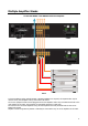
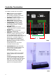
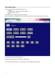
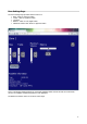
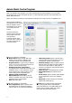

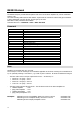
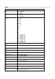
Table Of Contents
- Important Safety Instructions
- Precautions
- DECLARATION OF CONFORMITY
- We declare under our sole responsibility that this product, to which this declaration relates, is in conformity with the following standards:
- EN60065, EN55013, EN55020, EN61000-3-2 and EN61000-3-3.
- Following the provisions of Low Voltage Directive 2006/95/EC and EMC Directive 2004/108/EC, the EC regulation 1275/2008 and its frame work Directive 2009/125/EC for Energy-related Products (ErP).
- A NOTE ABOUT RECYCLING:
- This product’s packaging materials are recyclable and can be reused. Please dispose of any materials in accordance with the local recycling regulations.
- When discarding the unit, comply with local rules or regulations. Batteries should never be thrown away or incinerated but disposed of in accordance with the local regulations concerning battery disposal.
- This product and the supplied accessories constitute the applicable product according to the WEEE directive.
- Precautions
- For U.S. models
- For Canadian Models
- 1 Front Panel
- 1 AC Inlet
- 2 Speaker Terminals
- Amplifier Section
- General
Controller Termination
The 400DA is packed with control options:
• USB: Intended for initial installation
Programming or firmware update.
Not intended for permanent connection
to a PC or other control system.
• ETHERNET: 100BaseT connection to a
Home network router or switch.
• RS232 Serial: Electrically isolated
Prevents hum in analog input circuits.
• CONTROLLERS: Conveys +12VDC,
IR and Data between the 400DA and
Axium keypad controllers, connected
using CAT5 cables.
• BUS RUN: (Legacy) Port conveys
+12VDC, IR & Data to remotely connected
IR controllers.
• AMPON: +12VDC 100mA trigger
output when a Zone is ON.
• PRESETS: P1 and P2 Inputs are active low.
Connect C (common) and either P1 or P2
across an illuminated door bell switch.
The illuminated doorbell switch must have an
External 12V – 24V AC/DC supply and
current limiting resistor connected.
If a dry contact is to be used for PRESET
Activation, it must be normally closed or a FIG 3
Push to break contact.
The BUS RUN 0V and +12V can be
connected as shown in FIG 3
• EXPANSION BUS: Simple Patch cable
interconnection for Axium amplifiers that
conveys control and data between
amplifiers in a stack.
The cable length must be < 0.5m.
Interconnection to older Axium amplifier
models is possible only for the Control
functions.
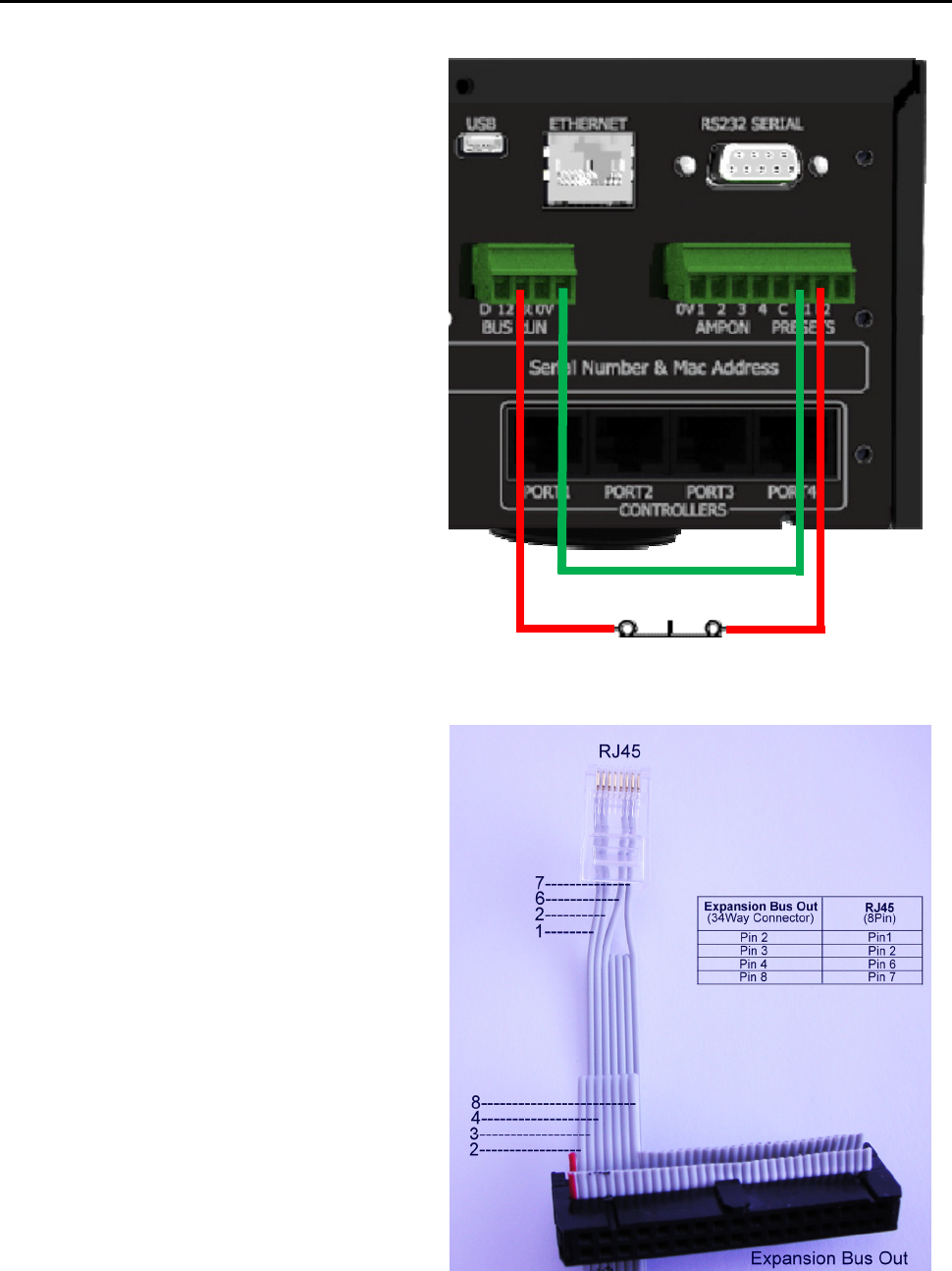
A special cable must be made. See FIG 4.
In older Axium amplifier models Analog
audio was conveyed through a 34 way IDC
cable. This is no longer supported, and
connections must be done using RCA
splitters in the analog audio inputs.
FIG 4
13