
Instruction manual


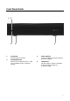
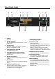

Table Of Contents
- Important Safety Instructions
- Precautions
- DECLARATION OF CONFORMITY
- We declare under our sole responsibility that this product, to which this declaration relates, is in conformity with the following standards:
- EN60065, EN55013, EN55020, EN61000-3-2 and EN61000-3-3.
- Following the provisions of Low Voltage Directive 2006/95/EC and EMC Directive 2004/108/EC, the EC regulation 1275/2008 and its frame work Directive 2009/125/EC for Energy-related Products (ErP).
- A NOTE ABOUT RECYCLING:
- This product’s packaging materials are recyclable and can be reused. Please dispose of any materials in accordance with the local recycling regulations.
- When discarding the unit, comply with local rules or regulations. Batteries should never be thrown away or incinerated but disposed of in accordance with the local regulations concerning battery disposal.
- This product and the supplied accessories constitute the applicable product according to the WEEE directive.
- Precautions
- For U.S. models
- For Canadian Models
- 1 Front Panel
- 1 AC Inlet
- 2 Speaker Terminals
- Amplifier Section
- General

Features
Thank you for purchasing an Axium AX-400DA Multi-Zone Amplifier.
Please read this manual thoroughly before making connections and plugging in the unit.
Following the instructions in this manual will enable you to obtain optimum performance and
listening enjoyment from your new Multi-Zone Amplifier.
Please retain this manual for future reference.
Multi-Zone, Multi-Source, Video Switching
The 400DA amplifier has four separate amplifiers
providing 4 zones of independent yet integrated
control.
There are 6 input sources comprising the
following:
Sources 1 – 3 are either Analog Stereo, or Coax
Digital Audio (PCM).
Sources 4 & 6 are Coax Digital Audio (PCM)
In addition there is a internally generated Door-
Bell source - .wav playback source - typically used
for paging applications.
Zone Outputs
Each zone has bass, treble, balance and loudness
control.
A feature called ‘Maximum Volume limiting’, is
useful for protecting connected speakers.
Amplifier Power, Protection, and Clipping
Indicators
50 Watts RMS per channel into 8 ohm loads.
Capable of driving into 4 ohm loads.
The amplifiers are protected against output
shorts, and have algorithms that prevent hard
clipping when the zone amplifiers are overdriven.
Thermal Control
There are two progressive levels of thermal
control:
• The amplifier volume is reduced 20dB.
• The amplifiers are shutdown until the
temperature reduces below the first level.
Care should be taken to ensure adequate
ventilation – see “Important safety instructions”
on page 1
Ethernet, RS232, USB and IR control
The 400DA amplifier may be controlled and
monitored via the rear Panel USB, RS232 serial
interface or Ethernet.
A Web application is available where full control
can be accessed using a suitable Web browser
running on a PC, Tablet or Smart Phone.
In multi amplifier installations where the
amplifiers are interconnected using an expansion
bus cable, only one Ethernet or RS232 connection
is required to control the stack of amplifiers.
The 400DA amplifier may receive IR directly from
the front panel receiver or via the four ‘Controller’
connections.
There are zone specific IR commands and also a
set of global IR commands.
The commands are: ON, OFF, Standby (toggling),
Mute, Volume Up, Volume Down, Source Selects,
Discrete Audio Source Selects, On with Source
Specific commands.
The Global commands also include PRESET1 –
PRESET 14, Alarm Enable, Alarm OFF, & 5 minute
Sleep.
Real Time Clock
The 400DA amplifier is equipped with a real time
clock.
The amplifier may be set up to function as an
alarm clock, so that at 6.30am in the morning 5
days a week, the master bedroom zone could be
made to turn on, select tuner, and go to a specific
volume. Multiple Alarms are feasible (max of 14)
however the Alarm Enable & OFF commands act
upon all programmed Alarms.
The Clock automatically compensates for daylight
saving.
The clock continues to operate typically > 48
hours without power – more than enough to keep
the time current during lengthy power outages
.
IR Emitter Ports
There are 8 Buffered IR emitter Ports.
Ports 1 – 6 have IR routing, and are intended to
control specific input source components. Two IR
ports; ‘SUM IR1-IR6’ are the sum of all IR sources
and control the ‘All’ zone source components.
6