
Instruction manual


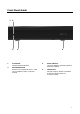
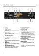

Table Of Contents
- Important Safety Instructions
- Precautions
- DECLARATION OF CONFORMITY
- We declare under our sole responsibility that this product, to which this declaration relates, is in conformity with the following standards:
- EN60065, EN55013, EN55020, EN61000-3-2 and EN61000-3-3.
- Following the provisions of Low Voltage Directive 2006/95/EC and EMC Directive 2004/108/EC, the EC regulation 1275/2008 and its frame work Directive 2009/125/EC for Energy-related Products (ErP).
- A NOTE ABOUT RECYCLING:
- This product’s packaging materials are recyclable and can be reused. Please dispose of any materials in accordance with the local recycling regulations.
- When discarding the unit, comply with local rules or regulations. Batteries should never be thrown away or incinerated but disposed of in accordance with the local regulations concerning battery disposal.
- This product and the supplied accessories constitute the applicable product according to the WEEE directive.
- Precautions
- For U.S. models
- For Canadian Models
- 1 Front Panel
- 1 AC Inlet
- 2 Speaker Terminals
- Amplifier Section
- General
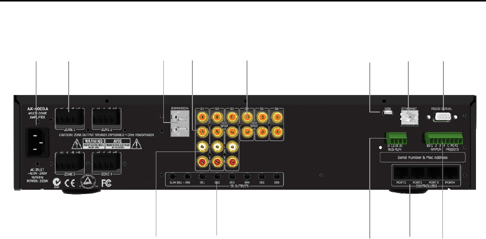
Rear Panel Guide
1 2 3 4 5 6 7 8
9 10 11 12 13
1 AC Inlet
IEC socket
2 Speaker Terminals
Plug in terminal clamp connectors accept 1.5mm²
speaker wires
3 Expansion Bus
RJ45 patch cable connects between expansion
bus ports of amplifiers in a stack.
4 Coax Digital Input Terminals
Coax digital (SPDIF) inputs.
5 Coax Digital Source Output Terminals
Coax digital outputs for expansion to further
amplifier zones.
6 USB for programming
USB mini B socket for programming and firmware
updates.
7 Ethernet Port
This port is used for control, monitoring and data
access.
8 RS232 Communication Port
The port is used for setup, control or monitoring.
A straight through cable must be used when
connecting to a PC or control system.
9 Analog Input Terminals
Analog Audio L/R inputs
10 IR Emitter Ports
3.5mm mono jacks.
IR1 and IR6 are used to control specific source
equipment, where full IR routing is assigned by
the connected controller.
SUM IR1 – IR6 are used to control source
equipment common to all zones. These ports
output the combined IR1 – IR6 infra-red strings.
11 Bus Run Controller Interface
Legacy ‘BUS RUN’ port (4 way terminal block)
12 Controller Interface
For connection to keypads and IR receivers.
4 controller interface ports - RJ45 sockets
13 AMP ON Control
12 – 24V AC/DC powered doorbell - contact
closure between PG1 or PG2 and Common (C)
terminals invokes a preset, enabling paging or
doorbell function.
AMP-ON 1 - 4 output 12VDC when their Zone
Standby is ON.
9