AXMINSTER Hobby Code 505020 Code 505021 SERIES AH-1218 & AH-1218VS Woodturning Lathes
Index of Contents Index of Contents Declaration of Conformity What’s Included General Instructions for 230V Machines Specification Assembly Illustration and Parts Description Operating Instructions Removing the Faceplate Removing Drive/Live Centres Maintenance Parts Breakdown Parts List Wiring Diagram 02 02 03 04 05 05-06-07 08-09-10 11-12-13 13 14 14 15 16-17-18 19 Declaration of Conformity Copied from CE Certificate Manufactured by Laizhou Chunlin Machinery Co.
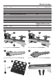
What’s Included Quantity Item Part 1 No 1 No 1 No 1 No 1 No 1 No 1 No 1 No 1 No 1 No AH-1218 Wood Lathe (Index Lock not fitted to the lathe) AH-1218VS Wood Lathe (Index Lock not fitted to the lathe) Banjo arm (fitted) 150mm Tool rest (fitted to banjo arm) 75mm Faceplate (fitted to headstock) Axminster 4 Prong Drive Centre (25mm) Axminster Standard 60˚ Live Centre Push Rod Tool Holder and two Phillips screws/washers Tailstock handle A B C D E F G H I J Model Number 1218A (505020) 1218DA (505021) (code
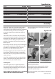
General Instructions for 230V Machines Do not work with cutting tools of any description if you are tired, your attention is wandering or you are being subjected to distraction. A deep cut, a lost fingertip or worse; is not worth it! Above all, OBSERVE…. make sure you know what is happening around you, and USE YOUR COMMON SENSE.
Specification Model Code Rating Power Speed Spindle Taper Spindle Thread Taper Tailstock Distance Between Centres Max Diameter over Bed Tool Rest Stem Diameter Overall L x W x H Weight AH-1218 505020 Hobby 600W (230V) (5) 500-3,150 rpm MT2 1” x 8tpi (Ref T04M) 2MT 457mm 305mm 16mm 820 x 440 x 280mm 40kg Model AH-1218VS Code 505021 Rating Hobby Power 550W, 230V Speed (2) 500-2,040 and 1,000-4,080 Spindle Taper MT2 Spindle Thread 1” x 8tpi (Ref T04M) Taper Tailstock 2MT Distance Between Centres 457mm Max Di
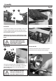
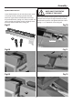
Assembly Fig 01-02 Fig 05 F G Fig 06 Tool Holder Locate the tool holder (I) the two Phillips screws and washers. (see fig 3) Place a washer over the screws and screw them into the two pre-drilled holes below the headstock, (see fig 4). NOTE: There are also two pre-drilled holes under the tailstock if you wish to mount the tool holder there.
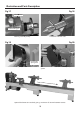
Assembly Optional Bed Extension NOTE: DON’T TIGHTEN THE SCREWS AT THIS POINT! Locate the bed extension (K) and the two Hex screws and spring/washers, (see fig 7) position the bed extension against the end of the lathe and line up the pre-drilled holes, (see figs 8-9). Place a washer and spring washer over the Hex screws and lightly screw them into the threaded holes, (see fig 10).
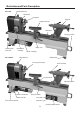
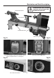
Illustration and Parts Description AH-1218 Headstock cover Headstock Faceplate Tailstock 150mm Tool rest Lathe bed Carrying handle Lower pulley door lock NVR switch assembly Banjo arm Motor assembly Index lock pin AH-1218VS Rubber foot 4 Prong drive centre 60˚Live centre Tool rest lock Tailstock handle Motor handle lock Motor handle Push rod tool holder Banjo arm lock Start (ON) Stop (OFF) 8 Variable speed control
Illustration and Parts Description WARNING! MAKE SURE THE INDEX LOCK PIN IS IN THE UP POSITION BEFORE SWITCHING ON.
Illustration and Parts Description Fig 17 Fig 18 Index pointer Index locking pin Indexing assembly facility Tailstock barrel with scale Fig 19 Fig 20 Door knob spring lock Motor pulley access door Lower the headstock cover to reveal the pulley system Optional bed extension attached giving a maximum of 965mm between centres 10
Operating Instructions Indexing Facility The indexing facility is useful for fluted columns, clock faces and accurate hole positioning. Lift and Rotate the index locking pin knob to unlock the headstock spindle, turn the faceplate and line up one of the positions then lower the indexing pin to lock the spindle in position, (see figs 21-22-23-24).
Operating Instructions Fig 27 Changing the Lathe Speed PLEASE NOTE THE FOLLOWING PICTURES SHOW THE AH-1218 LATHE. DISCONNECT THE LATHE FROM THE MAINS SUPPLY BEFORE CONTINUING! 1. Open the motor pulley access door by pulling the door knob back, (see figs 25-26). Lower the headstock cover to access the pulleys, (see fig 27). 2. Release the motor handle lock and lift the motor up, tighten the handle to lock the motor in position, this releases the tension on the pulleys (see figs 28-29).
Operating Instructions 3. Reposition the belt to one of the five positions on the pulleys, (see figs 30). Lathe Pulley Speed Chart Spindle MAKE SURE THE BELT IS INSERTED CORRECTLY INTO THE PULLEY GROOVES! Fig 30 4080 rpm 1000rpm 2400 rpm 500 rpm 3150 rpm 2000 rpm 1430 rpm 500 rpm 4. Lower the motor to put tension back on the pulleys and lock in position. Raise the headstock cover and close the motor access door.
Removing Drive/Live Centres To remove the Drive Centre (F), locate the push rod (H), while holding the Drive Centre insert the push rod (H) through the centre hole of the headstock wheel and push the Drive Centre (F) out (see fig 31). Repeat the procedure for the Live Centre (G) in the tailstock (see fig 32). Fig 31 Fig 32 G H H F Maintenance Daily after use Monthly • Clean wood shavings away from the lathe bed and tool rest.
Parts Breakdown 15
Parts List 1218VDA (AH-1218VS) No. 1 Description Washer ø4 Qty No.
Parts List No. Description Qty No.
Parts List No. Description Qty No.
Wiring Diagram 19
The Axminster guarantee is available on Hobby, Trade, Industrial, Engineer, Air Tool & Axcnc Technology Series machines It’s probably the most comprehensive FREE guarantee ever- buy with confidence from Axminster! So sure are we of the quality, we cover all parts and labour free of charge for three years! • Look for the icon and put your trust in Axminster • No registration necessary - just keep your proof of purchase • Optional Service Plan for Industrial Series machinery Great value & easy-to-use, perfec