
Operating instructions

5
Specication
Model AH-1218
Code 505020
Rating Hobby
Power 600W (230V)
Speed (5) 500-3,150 rpm
Spindle Taper MT2
Spindle Thread 1” x 8tpi (Ref T04M)
Taper Tailstock 2MT
Distance Between Centres 457mm
Max Diameter over Bed 305mm
Tool Rest Stem Diameter 16mm
Overall L x W x H 820 x 440 x 280mm
Weight 40kg
Model AH-1218VS
Code 505021
Rating Hobby
Power 550W, 230V
Speed (2) 500-2,040 and 1,000-4,080
Spindle Taper MT2
Spindle Thread 1” x 8tpi (Ref T04M)
Taper Tailstock 2MT
Distance Between Centres 457mm
Max Diameter over Bed 305mm
Tool Rest Stem Diameter 16mm
Overall L x W x H 820 x 440 x 280mm
Weight 40kg
Assembly
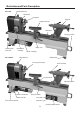
Please take some time to read the section entitled
“Illustration & Parts Description” to identify the
various parts of your machine so that you are familiar
with the terminology we will use to enable you
to set up and operate your table lathe safely and
correctly.
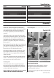
The machine and its accessories will arrive coated
with corrosion preventative grease. This will need to
be cleaned from the machine, its components and
accessories prior to it being set up. Use coal oil,
paraffin or a proprietary de greaser to remove the
barrier grease.
Be warned, it will stain if you splash it on clothing etc.,
wear overalls, coverall et al., rubber gloves are also a
good idea, as is eye protection if your cleaning
process tends to be a little bit enthusiastic.
After cleaning, lightly coat the machine with a thin
layer of light machine oil. N.B If you used paraffin/
kerosene make sure you apply this thin film sooner
rather than later.
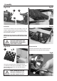
95% of the machine comes fully assembled, all that
remains is to fit the four prong drive centre (F) the
60˚ live centre (G) and the tool holder (I).
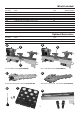
Fig A-B-C-D
Continues Over...
Removing the plug
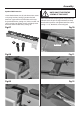
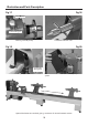
Fitting the indexing lock Securely tighten
The indexing lock is know supplied separately in
the accessory pack and not fitted to the lathe. We
recommend to fit the index lock only if you plan to
use the index facility in the future.
NOTE: DO NOT USE THE INDEX LOCK AS A SPINDLE
LOCK AS YOU WILL DAMAGE LOCKING PIN.
Please see figures A-B-C-D for fitting instructions for
the indexing lock.
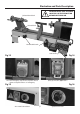
Locate the four prong drive centre (F) and slide
it through the centre of the faceplate into the
headstock spindle (see fig 1).
Locate the live centre (G) and slide it into the tailstock
barrel (see fig 2).
Drive Centre/Faceplate
Indexing Lock