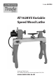
Code: 502703 AT1628VS Variable Speed Wood Lathe Axminster Tool Centre, Unit 10 Weycroft Avenue, Axminster, Devon EX13 5PH www.axminster.co.
Index of Contents Index of Contents Declaration of Conformity What’s Included Optional Accessories General Instructions for 230V Machines Specific Safety Instructions for Woodturning Lathes Specifications Assembly Instructions Lathe Assembly Lathe Stand Assembly Lathe Extension Assembly 1 and 2 Illustration and Description Operating Instructions Rotating the Headstock Removing the Faceplate Indexing Facility Removing the Drive Centre Changing the Belt Speed Maintenance Parts Breakdown/List Wiring Diagram No
What’s Included Quantity Item Part 1 No Variable Speed Wood Lathe A 1 No Spanner B 1 No Push Rod C 1 No Spindle Lock Pin D 1 No Motor Plate Handle E 1 No Instruction Manual B Model Number 1628INV E C D Optional Accessories Quantity 1 No 4 No 1 No Item Lathe Extension 3/8” x 1 3/4” Hex Bolts & 8 No 3/8” Washers Tool Rest Extension Part H 2 No 8 No 4 No Lathe Stand 3/8" x 11/2" Bolts & 16 No 3/8" Washers Feet F Code Number 502704 I 502705 G G F I H 3
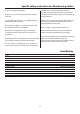
General Instructions for 230V Machines It is good practice to leave the machine unplugged until work is about to commence, also make sure to unplug the machine when it is not in use, or unattended. Always disconnect by pulling on the plug body and not the cable. Once you are ready to commence work, remove all tools used in the setting operations and place safely out of the way. Re-connect the machine.
Specific Safety Instructions for Woodturning Lathes 1. Do not use ‘split’ work pieces. faceplates etc.,) can be ‘locked’ onto the lathe mandrel, and in the case of chucks have some form of security device to prevent them ‘unwinding’ during reverse operation. 2. Always start at the lowest speed when starting a new task. 8. Make sure your tools are stored/racked away from the turning area of the lathe. Do not reach over a rotating workpiece at any time. 3.
Assembly Instructions Please take some time to read the section entitled “Illustration and Description” to identify the various parts of your machine so that you are familiar with the terminology we will use to enable you to set up and operate your table lathe safely and correctly. be cleaned from the lathe, its components and accessories prior to it being set up. Use degreaser to remove the barrier grease. Be warned, it will stain if you splash it on clothing etc.
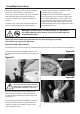
Assembly Instructions Figure 04 Figure 07 b Figure 05 Figure 08 A Figure 06 Figure 09 F 3. Lift the lathe bed from the pallet onto a work bench, see figs 7 then refit the headstock, tool rest and tailstock as described in steps 1 and 2, see figure 8 G Lathe Stand Assembly (Code: 502705) 1). Locate the two lathe stands (F) and the four feet (G).Screw the threaded feet into the pre-drilled holes to the base of the stands. (See figure 9) 7 Continues Over...
Assembly Instructions Figure 13 Remove the headstock, tool rest assembly and tailstock from the lathe bed as before to make it easier to assemble the stands 2. After removing the above lift the lathe bed using a scissor lift, lifting host or seeking help. 3. Place the stands (F) to each end of the lathe bed and line up the holes in the stands with threaded holes in the lathe bed, secure using the 3/8" bolts and washer (c),see figures 10-11-12-13. 4. Replace the headstock, tool rest and tailstock.
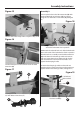
Assembly Instructions Figure 15 Assembly 2 1. Line up the holes in the lathe extension (H) with the threaded holes in lathe stand (F) and secure using the 3/8” Hex bolts and washers (d), see figure 18. Figure 18 H Remove the tailstock stop “PIN” and place safely aside Figure 16 d Using the 3/8” Hex bolts and washers (d), secure the lathe extension in position 2. Release the headstock lock and slide the headstock down to the end of the lathe bed and lock in position.
Illustration and Description Motor locking handle Headstock Tailstock Faceplate Live centre Tool rest Banjo lock Tool rest lock Headstock pivot lock Headstock locking handle Control box Spindle speed LED Tailstock wheel Access panel Tailstock barrel lock Lathe bed Tailstock lock stop Tailstock lock Banjo 10 Motor plate handle
Illustration and Description ON OFF The control box has a magnetic base enabling it to be positioned anywhere on the lathe ON (Green) and OFF (Red) buttons Forward and Reverse switch The Speed Control Knob, enables you to increase or decrease the speed of the spindle Indexing ring Index lock pin Headstock Pivot Lock, pull this knob to rotate the headstock to the desired position Indexing ring facility and locking pin is used for fluted columns, clock faces and accurate hole positioning 11
Operating Instructions Figure 20 Rotating the Headstock The Headstock can be swivelled in any position by lifting up the Headstock locking handle (a) and pulling the Headstock pivot lock (b) out, swivel the Headstock to the desired position is reached, lock in place by pushing down the headstock locking handle (a). (See figure 18) The Headstock incorporates two index positions 45˚and 90˚, swivel the headstock until it locks in place to allow bowls to be turned in front of the lathe.
Operating Instructions Figure 25 Indexing facility DISCONNECT THE LATHE FROM THE MAINS SUPPLY Drive centre The Indexing ring is situated to the left side of the headstock which incorporates 36 positions at (10˚) segments. To the side of index ring is the index locking pin to lock the spindle in position. The indexing facility is useful for fluted columns, clock faces and accurate hole positioning. (See figure 23) C Figure 23 Index ring Repeat the procedure for the live centre in the tailstock.
Operating Instructions Figure 27 Reposition the belt, making sure the groves in the belt slot into the groves in the pulleys. Pull/push the motor assembly until the belt is under tension, retighten the motor locking handle (a). (See figure 27) Close the pulley access panel and replace the Hex screw. Maintenance The woodturning lathe has little maintenance, but it is advised to do the following checks to keep the lathe in good working order.
Parts Breakdown/List Headstock Assembly A 15
Parts Breakdown/List Headstock Assembly A 16
Parts Breakdown/List Headstock Assembly A 17
Parts Breakdown/List Body Assembly B 18
Parts Breakdown/List Body Assembly B 19
Parts Breakdown/List Stand Assembly C (Optional) 20
Parts Breakdown/List 21
Wiring Diagram 22
Notes 23
Please dispose of packaging for the product in a responsible manner. It is suitable for recycling. Help to protect the environment, take the packaging to the local recycling centre and place into the appropriate recycling bin. Only for EU countries Do not dispose of electric tools together with household waste material.