Code 501251 AW12BM 12mm Bench Morticer Axminster Tool Centre, Unit 10 Weycroft Avenue, Axminster, Devon EX13 5PH axminster.co.
Index of Contents Page No Index of Contents Declaration of Conformity What’s in the Box Initial Actions General Instructions for 230V Machines Initial Assembly Specification Parts Identification and Description Setting up the Machine General Precautions Whilst Using a Drilling Machine Maintenance Parts Breakdown/List 02 02 03 04 04-05 05-06 06 07-08-09-10-11-12-13 14-15-16 16-17 17 18-19 Declaration of Conformity Copied from CE Certificate The undersigned, F.
What’s in the Box Quantity 1 No. Item Model Number Mortising Machine Base with Mounting Columns, Plunge Depth Stops, Balance Spring, Head Box, Chisel Adaptor, Chuck and Fence Mounting Block assembled MS3612 1 No. 12mm Auger Chisel and Bit Set 1 No. Composite Board Machine Table 1 No. Back Fence with Main Mounting and Hold Down Mounting Rods Fitted 1 No. Large Tensioning Spring 1 No. Lift and Shift Locking Handle 1 No. Fence Adjusting Assembly 1 No Hold Down Yoke 1 No. 1 No.
Initial Actions Having unpacked your machine and its accessories, please check the contents against the equipment list ”What’s in the box”, if there are any discrepancies, please contact Axminster Power Tool Centre using the procedures laid down in the catalogue. Please dispose of the packaging responsibly; much of the material is bio-degradable. The machine and its accessories will arrive coated with heavy corrosion preventative grease and greased wax paper.
General Instructions for 230V Machines ! ! Keep the work area as well lit and uncluttered as is practical, this includes personnel as well as material. Under no circumstances should CHILDREN be allowed in work areas. It is good practice to leave the machine unplugged until work is about to commence, also make sure to unplug the machine when it is not in use, or unattended. Always disconnect by pulling on the plug body and not the cable.
Initial Assembly of the Machine 2) Locate the Accessory tray, the small ‘P’ clip and the three small panhead screws. Locate the 3 No. threaded holes in the rear upper left side of the headbox. Snap the ‘P’ clip on the cable, tidy’ the mains cable away from the front of the machine, and secure into the most forward threaded hole. Offer up the accessory tray and secure using the remaining two panhead screws, into the threaded holes. 3) Locate the backfence and its associated components.
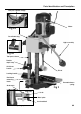
Parts Identification and Description Large head machine screw Fig 1 Rise and fall Mechanism Motor Fig 1a Plunge lever assembly Chuck access door Depth stop bolt Lamp Fig 1b Lock nut Chisel clamping bolt Backfence Fig 1c Chisel mounting flange Base casting Mortising table 07
Parts Identification and Description ! Please take some time to identify the various parts of your machine so that you are familiar with the terminology we will use to enable you to set up and operate your morticer safely and correctly. Base Casting (See fig 1) This is the ‘Stand’ for the mortising m/c. It has a square flat table machined at the front, onto which a machine table board can be fitted.
Parts Identification and Description Tool post column bridge Motor Fig 2a Castellated dog Light assembly Fig 2b Tool post column Double depth stop Shift lever handle Chisel Locking handle Backfence mounting block Counterbalance spring Grubscrew Fig 2 Fig 2c Scale Metal plate Star knob bolt Fine adjusting system 09
Parts Identification and Description Tool post columns (See fig 2) Two steel shafts mounted into the rear of the base casting, they are the ‘runners’ for the headbox. They are ‘bridged’ at the top to increase accuracy and rigidity, The machine lamp is mounted on the bridging lozenge. The right hand column has a rack cut in the surface which engages with a pinion in the headbox assembly to provide the rise and fall action.
Parts Identification and Description NVR on/off switch assembly Fig 3a On Motor Grip Sleeve Off Handle Headbox casting Chuck door removed for clarity Fig 3b Fig 3 Auger mounting chuck Backfence mounting block Spring Fig 3c 11
Parts Identification and Description Hold Down Yoke This is a small ‘U’ shaped yoke casting. The underside of the arms of the ‘U’ (See fig 4b) are flat, to rest on the workpiece. In the middle of the yoke is a land sufficiently large enough to be bored through to accept the mounting rod. There is a grubscrew threaded through the wall of the hole so that the hold down can be secured in position.
Parts Identification and Description Morticer converted to a drill press Drill press assembly Fig 5 Chisel mounting clamp bolt Fig 5c Chuck guard Fig 5a B6 to parallel chuck mounting shaft Chuck mounting shaft 1-13mm/B6 drill chuck Fig 5b Chuck key Fig 5d 1-13mm/B6 drill chuck assembly Fig 5e Drill bit Auger chisel 12mm auger chisel & bit set 13
Setting up the Machine Overview Unlike the traditional morticing machines, which allow the table to move in 2 axis, i.e. side to side and front to rear, the table of this morticer does not move at all. The workpiece must be moved to achieve the side to side movement, and the placement of the back fence simulates the front to rear movement. Initial Set up Introduce the chisel into the adaptor collar, press the auger up into the chuck, tighten the chuck and withdraw the chuck key.
Setting up the Machine General Notes The morticer will generate a lot of ‘grip’ on the chisel, especially the first cut, or if the timber is a little green. Make sure you use the hold down yoke to help control the timber during the raise operation of the morticer. A lot of setting and resetting is required for the various components of the morticer.
Setting up the Machine Quick Setting of the Mortice Depth Put a mark on an easily accessible end of the workpiece to be mortised, at the depth you require. Pull the headbox down, and put the end of the timber against the chisel, position the headbox so that the chisel points or the auger point are at the depth required, raise the depth stop collar to the underside of the headbox and tighten gently.
General Precautions Whilst Using a Drilling Machine 9. It is a good precaution to wear eye protection when drilling, especially using small drills, or very hard material that produces small chips. 10. It is not a good idea to wear gloves when operating a drill press. 11. After the job is completed, remove all tools and accessories from the machine, check that drill bits are still sharp and re-useable. Clean the machine down thoroughly, including removing coolant or cutting compounds from the drill table.
Parts Breakdown/List 18
Parts Breakdown/List Ref No Description Unit Ref No Description Unit 1 Motor 36 Handle assembly 2 Power cord 37 Bolt 3 Chuck 38 Cap screw M8 x 10 4 Key 39 Guide 5 Head 40 Bracket 6 Label 41 Lock washer 7 Hex head bolt M8 x 20 42 Hex head bolt M8 x 15 8 Bushing 43 Table 9 Guide sleeve 44 Hex head screw M6 x 35 10 Position plate 45 Fence 11 Flat washer 10 46 Cap screw M8 x 10 12 Hex head bolt M10 x 35 47 Hold down 13 Holder 48 Cap screw M8 x 10 14 Cap s
Please dispose of packaging for the product in a responsible manner. It is suitable for recycling. Help to protect the environment, take the packaging to the local recycling centre and place into the appropriate recycling bin. Only for EU countries Do not dispose of electric tools together with household waste material.