
Instruction manual


Parts Identification and Description
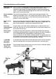
Hold Down Yoke This is a small ‘U’ shaped yoke casting. The underside of the arms of the ‘U’
(See fig 4b) are flat, to rest on the workpiece. In the middle of the yoke is a land
sufficiently large enough to be bored through to accept the mounting rod.
There is a grubscrew threaded through the wall of the hole so that the hold
down can be secured in position.
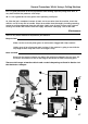
Chisel mounting The chisel mounting flange is a raised annular housing machined at the
flange bottom of the headbox. It has a 3/4" adaptor pressed into it, which is used to
(See fig 1c) clamp the chisels in position. It is also used to mount the guard when the
morticer is used in ‘Drill’ mode.
Chuck access Access to the chuck for loosening or tightening is via a rectangular hole in
door the front of the headbox casting. This hole is covered by a hinged door. The
(See fig 1) door is held closed by a sprung catch moulded into the door.
Accessory A plastic block, with various holes moulded into it to allow the chisel sets,
mounting panel chuck key, allen keys etc, of the machine tool kit, to be stowed safely out of
(See fig 4a) the way but close to hand.
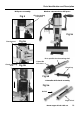
Chuck guard A hinged and telescopic guard that is fitted to the headbox lower bearing
(See fig 5a) flange during drilling operations. (Remove the bolt for the chisel clamping) It
has a spring fitted to the hinge geometry to hold the guard “over
centre” to maintain it in the raised or lowered position. The guard shield can
be extended or retracted (telescoped) as required, using the second leaf, the
second leaf is held in position by two butterfly nuts and bolts.
1-13mm/B6 A standard 12mm chuck with an internal B6 taper mount. Used in conjuction
drill chuck` with the mounting shaft to transpose the mortiser into a small drill press.
(See fig 5d)
B6 to parallel The mounting shaft for the drill chuck, the main shaft has a diameter slightly
shank shaft smaller than the adaptor for the chisels.
(See fig 5d,5e)
Accessory mounting panel Hold down yoke
Fig 4
Fig 4a
Fig 4b
12