
Instruction manual


08
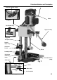
Parts Identification and Description
Please take some time to identify the various parts of your machine so that you
are familiar with the terminology we will use to enable you to set up and operate your
morticer safely and correctly.
Base Casting This is the ‘Stand’ for the mortising m/c. It has a square flat table machined at
(See fig 1) the front, onto which a machine table board can be fitted. There are several
holes and slots in the base through which you could fasten the base to a
bench or similar to give added stability if you so desire. At the rear of the
base are the housings for the tool posts.
Fine adjusting The fine adjusting system consists of a metal plate bored through to fit over
system the backfence main mounting bar, beyond the mounting block. The plate is
(See fig 2c) held in position by a grubscrew threaded through the wall of the hole and
screwed down against the main mounting bar. There is also a threaded hole
through the plate, through which a long star knobbed bolt is fitted. This bolt
acts against the lower part of the backfence mounting block and is used to
adjust the backfence against the spring tension. If the reach of the bolt is
exceeded during adjustment, the plate can be further adjusted along the main
mounting bar.
Mortising table The Mortising table is a piece of composite board which is screwed down to
the (See fig 1) base casting to provide a large flat area on which to mount the work piece.
Counterbalance A large coil spring is mounted over the left hand side tool post column. It acts
spring between the machine base and the underside of the headbox, and in
(See fig 2) compression, acts as a counterbalance to the weight of the headbox
assembly.
Double depth Two ring collars that fit over the right hand side tool post column below the
stop head box. The lower collar has a threaded through hole into which a lift and
(See fig 2) shift lever handle bolt is inserted. Tightening this bolt will clamp the collar into
position on the tool post column and govern the position of the upper collar.
The upper collar has a bolt with a lock nut threaded into the upper face of the
collar, this bolt can be adjusted and locked. Turning the head of the nut under
the head box, or turning the head of the bolt out from under the head box will
give two separate plunge depths.
Backfence This is a casting with a machined front face and a flat underside. There is a
(See fig 1) large land in the middle of the casting behind the front face; this land has the
main mounting bar fitted to it, which extends to the rear; and is fed through
the backfence mounting block. There is a tension spring fitted concentrically
over the bar, which is compressed between the rear of the back fence and the
front of the backfence mounting block, which is part of the fence adjusting
system. There is also a housing machined in the top front of the land; into this
housing the support rod for the hold down is fitted; it can be adjusted in
height over part of its length and is held in place by a grubscrew inserted
through the wall of the housing.
Backfence This is a large block mounted on the base between the tool post columns. It
mounting block has a hole bored through it to accept the main mounting bar of the back
fence. There is a tapped hole through the top wall of the hole into which a lift
and shift locking handle is fitted, to secure the backfence at its required
dimension.
!