Code 951816 AWC20HP Air Compressor
Index of Contents Page Index of Contents Declaration of Conformity What’s Included Safety Precautions Specifications (AWC20HP Air Compressor) Assembly Instructions Illustration and Parts Description of Air Compressor Operating Instruction Maintenance Parts Breakdown Parts List Trouble Shooting 02 02 03 03 04 04-05 05-06-07 08 09 10 11 12 Declaration of Conformity manufactured by Qingdao D&D Electromechanical Technologies Co., Ltd.
What’s Included Quantity 1 off: 1 off 2 off 1 off 3 off Item Air Compressor 1 off M8 Spring Washer (D) Bottle of oil 2 off M8 nuts (E) Wheels (A) 1 off Filter Assembly (F) M8x50mm Bolt (B) 1 off Oil Filler Plug (G) M8 Washers (C) 1 off Instruction Manual Model Number RAC2024A Safety Precautions Good Working Practices/Safety The following suggestions will enable you to observe good working practices, keep yourself and fellow workers safe and maintain your tools and equipment in good working orde
Specification (AWC20HP Air Compressor) Code Rating Power Free Air Delivered Max Pressure Noise Level Receiver Volume Oil Capacity Supply Requirements Overall L x W x H Weight 951816 Hobby 1.4kW (230V) @ 40psi-5.0cfm, @ 90psi-4.0cfm 115psi 94dB 24 litres 300ml 10 Amps 570 x 300 x 590mm 22kg Assembly Instructions Remove the compressor from the packaging and check for damage or missing parts. Report any problems to Axminster Power Tool Centre’s Customer Services Department.
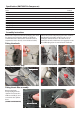
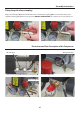
Assembly Instructions Fitting the quick release coupling Wrap some PTFE tape (A) around the thread on the 1/4” BSP male coupling (B) and screw it into the pressure regulator outlet, lightly tighten using a spanner. (DO NOT OVERTIGHTEN) The compressor is now ready for use.
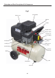
Illustration and Parts Description of Air Compressor Fig 1 Air inlet filter Motor cover Cylinder Handle On/Off switch Pressure switch 1/4” BSP male coupling Outlet pressure gauge Handle Crankcase Tank pressure gauge Oil drain plug Pressure relief valve Wheel Check valve Front foot 06 Tank
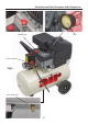
Illustration and Parts Description of Air Compressor Oil filler plug Filter Pressure adjuster Fig 2 Water drain valve 07
Operating Instructions The outlet air pressure can be regulated by rotating the regulator knob clockwise to increase the pressure and anticlockwise to reduce it. Do not leave the regulator set at maximum setting unnecessarily; reduce the setting by about two turns after finishing and then re-set to the required pressure when starting work again. drops below a pre-set level. The cut-in and cut-out pressures are factory set and should not need to be altered.
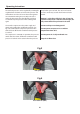
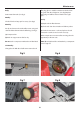
Maintenance Daily: Drain water from tank. (See fig 5) filler plug, place a suitable container under the drain plug and drain the oil right out. (See fig 8) Replace drain plug and refill to the level mark on the sight glass. Weekly: Yearly: Check oil level and top-up if necessary. (See fig 6) (a) Replace the air filter element. Monthly: (b) Check and clean the air intake and delivery valves.
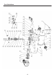
Parts Breakdown 10
Parts List Item Description in English Qty 34 Cylinder gaset 2 1 Tank assembly 1 35 Connecting rod 1 2 Hex nut 8 36 Piston 1 3 Spring washer 7 37 Oil clean ring 1 4 Plate washer 15 38 Seal ring 2 5 Wheel 2 39 Cylinder 1 6 Hexagon headed bolt 2 40 Valve plate gasket 1 7 Block 2 41 Right-angle connector 1 8 Seal washer 2 42 Bolt 4 9 Delivery pipe assembly 1 43 Air filter assembly 1 10 Spring washer 4 44 Cylinder cover 1 11 Cowl 1 45 Cylinde
Trouble Shooting PROBLEM CAUSE REMEDIAL ACTION Tank pressure drops. Leakage at connections or joints. Set the compressor to maximum pressure. Switch off and brush a soapy water solution onto all connections and joints. Look for bubbles. Tighten connections or joints where leakage is visible. The pressure switch valve leaks when the compressor is stopped Non-return valve seal dirty or defective Release any air in tank. Remove non-return valve seal. If necessary, replace the seal.