
Operating instructions


14
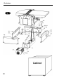
Illustration and Parts Description
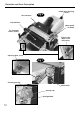
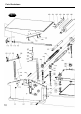
Stand assembly A preformed metal stand that encloses the motor. The main chassis
(See Fig 8) assembly is bolted to it. The whole is then bolted to the cabinet stand.
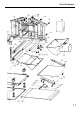
Main chassis The main body of the machine that all the other parts are mounted upon.
assembly
(See Fig 9)
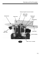
Infeed table The infeed table adjusting screw is held captive in a ring casting on the
adjusting front underside of the infeed table. It is a long length of rod with a
screw handle moulded on one end and a thread cut on the other. The threaded
(Unseen) part of the rod engages in a tapped hole in a cross bar of the main
chassis. Because the adjusting screw is held captive in the infeed table,
screwing the rod backwards and forwards will move the infeed table
backwards and forward on its slideways on the main chassis.
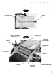
Infeed table The table that supports the material on the input side of the machine. It
(See Fig 8) moves up and down in a pair of inclined slideways machined in main
chassis, the level of the table is set relative to the top of the planer irons;
this setting governs the depth of cut that can be taken during the
overhand planing operation. The guide fence mounting bracket is
attached to the infeed table.
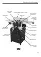
Thicknessing bed This handle is fitted to a crank arm formed on one of the threaded
rise and fall spindles that carry the thicknessing bed. There are four threaded
handle spindles that are connected by a chain drive in the lower part of the
(See Fig 9) main chassis assembly. The chain drive is tensioned by an idler gear,
which should be checked periodically.
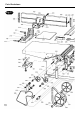
Outfeed or The table that supports the work after it has passed over the cutter block
take off table during the overhand planing operation. The level of the table is set to be
(See Fig 9) in line with the top of the plane irons, thus once the cutting action is
finished the table will support the workpiece during the remainder of the
planing pass. The outfeed table is removed for thicknessing operations,
to allow better access to the material passing over the thicknessing bed.
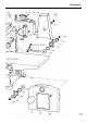
Upper cutter An aluminium extrusion covers the cutter block. It can be positioned
block guard both in height and laterally. It is mounted in a housing at the top of the
assembly support leg. The support leg has a rack machined into it which engages
(See Fig 9) with a pinion moulding which has a lever extrusion. Moving the lever up
and down will drive the support leg up and down, thus varying the height
of the upper guard. The guard mounting housing has a clamp set in it
which enables the guard to be clamped laterally.
Outfeed table These are the two clamps set on each side of the main chassis that
clamps clamp the outfeed table in position during the overhand planing
(See Fig 9) operation. The offside clamp position is also critical, in that it is part of
the interlock sequence, care must be taken to ensure the correct
configuration is met whilst setting the machine up for planing or
thicknessing. See the Operating Instructions.
Drive belt cover A moulded cover mounted on near side of the main chassis, secured by
(See Fig 8) a domehead nut.