
Operating instructions

09
Assembly
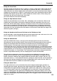
Fitting the Chip Deflection Cover
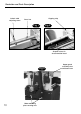
Fitting the Outfeed table
Fitting the Handle to the Rise and Fall Crank of the Thicknesser Bed
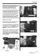
Identify the chip deflection cover and the 4 No. self-tapping screws and washers. Move to the
outfeed side of the machine and locate the aluminium extrusion mounted on the cross bar in
front of the anti-kick back fingers (See fig 5). Position the cover in the channel in the extrusion
and secure by screwing the self-tapping screws (with their washers), through the pre-formed
holes in the cover into the slot in the extrusion. The complete assembly should be able to pivot
around the cross bar, up and over the cutter block, or return into the void above the edge of the
thicknessing table (see fig 6).
Locate the handle, screw the projecting thread into the tapped hole in the crank arm as far as the
lock nut, tighten the lock nut down securely against the crank arm.
Open the Outfeed table clamps, (see fig 5). Raise the upper guard out of the way. Pivot the
chip deflector cover to the down position. Place the lugs of the outfeed table into the machined
rebates on the outfeed side of the machine. At the lower end of the mounting lugs are two
location brackets. The lower open slot in these location brackets fits over the peg dowels
screwed into the chassis (see fig 5). At the top end of the nearside lug is a small bracket (see fig
7) that depresses a sprung stop that then allows the nearside clamping lever to be turned to the
clamped position. This in turn moves a sprung bobbin which orientates a microswitch interlock to
indicate the machine is in ‘Planer Mode’. Press down firmly on the table, having ensured all the
locators are positioned correctly, turn the clamping levers to lock the table down.
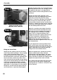
The guide fence components come fully assembled, but not tightened. Unscrew the bolt to
enable it to be slid into the slot in the mounting, position where required and tighten the lever
handle. The fence is bolted to the support bracket by two coach bolts, washers and nuts. The
coach bolts fit into a ‘T’ slot moulded in the fence (see fig 15). Adjust the ‘fore and aft’ position of
the fence to the position required and secure by tightening the nuts, make sure the “notch” on
the underside of the fence straddles the cutter block (see fig 8).
Fitting the Guide Fence
The angle of the fence can be set between the preset 0 degree and 90 degree positions by
loosening the lever handle, adjusting to the angle required and re-tightening. There is a scale
embossed on the support bracket casting to give a guide to the angle you are setting (see fig
14). The lever handles are the ‘lift’ to disengage type. e.g. if the lever is turned into a position
where it is fouling against the guide fence mounting bracket, pulling the handle up on its shaft,
against its spring keeper, will disengage the spline drive and can be moved freely away from the
obstruction. Allowing the handle to be sprung back will re-engage the spline and the handle will
again act as a lever.
Fitting the Infeed Table
The table should now be able to move, if it doesn’t, slacken a shade more. (Please note that the
adjusting movement is quite stiff, as the table lugs are captured with only a small clearance to
allow movement, but maintain rigidity when the machine is used in the overhand mode. Keep the
capping strip securing bolts as tight as is practically possible, whilst allowing the table to move).
Check the table moves up and down, at least between the extreme marks on the setting scale,
(remember you will have to take up the ‘slack’ when
you reverse direction of the table movement).