AWHBS350N, AWHBS310N Floor Standing Bandsaw 211530 (AWBS350N) Axminster Reference No: AWHBS350N Axminster Reference No: AWHBS310N w w w. a x m i n s t e r. c o .
Index of Contents... Page No. Index of Contents.................................................................................................................... 02 Declaration of Conformity………….………........……..………….........................................03 What’s in the Box………….………........……..…………...........................................................04 General Instructions for 240v Machines............................................................ 05-06 Unpacking..................................
Declaration of Conformity... W AXMINSTER W H I T E Copied from CE Certificate The undersigned, F. Mocking authorised by Laizhou City Fulin Electric Co., Ltd. No. 275 Wenquan East Road Laizhou, Shandong 261400 P.R. China declares that this product: Bandsaw MJ343B, MJ343C manufactured by Laizhou City Fulin Electric Co.
W What’s in the Box... AXMINSTER W H I T E Model Numbers: MJ343B (211530) MJ343C (211531) 1 No. Bandsaw 1 No. Bandsaw Blade (211530) 2480mm long 4 TPI Skip assembled in the saw...(not tensioned) 1 No. Bandsaw Blade (211531) 2270mm long 4 TPI Skip assembled in the saw...(not tensioned) 1 No. Saw Table 1 No. Fence Guide & Extension 1 No. Mitre Guide 1 No. Packet containing the On/Off Switch Safety Shroud 1 No. Table Insert Floor Cabinet comprising:2 No. Top Supporting Plate 2 No.
General Instructions for 240v Machines... W AXMINSTER W H I T E Good Working Practices/Safety The following suggestions will enable you to observe good working practices, keep yourself and fellow workers safe and maintain your tools and equipment in good working order. ! WARNING!! KEEP TOOLS AND EQUIPMENT OUT OF THE REACH OF YOUNG CHILDREN General Advice Mains Powered Tools Primary Precautions These machines are supplied with a moulded 13 Amp. plug and 3 core power cable.
W General Instructions for 240v Machines... AXMINSTER W H I T E ! (Under no circumstances should CHILDREN be allowed in work areas). It is good practice to leave the machine unplugged until work is about to commence, also make sure to unplug the machine when it is not in use, or unattended. Always disconnect by pulling on the plug body and not the cable. Once you are ready to commence work, remove all tools used in the setting operations (if any) and place safely out of the way. Re-connect the machine.
Cabinet Assembly... W AXMINSTER W H I T E Step 1 Support plate Base M6 x 12 bolts and washers. Step 2 Attach the two connecting plates. Lightly tighten the M6 x 12 bolts and washers.
W Cabinet Assembly... AXMINSTER W H I T E Cabinet door Step 3 Place the door between the support & connecting plates & insert the two spring hinge pins into pre-drilled holes. Spring hinge pin. Step 4 Side plate Locate the side plate and lightly secure using M6 x 12 bolts & washers. 08 Support plate Locate and secure the other support plate. www.axminster.co.
Cabinet Assembly... W AXMINSTER W H I T E Step 5 Attaching the rubber foot to the base of the cabinet Screw the four rubber feet into each corner to the base of the cabinet Step 6 Tighten all the M6 x 12 nuts, bolts and washers before mounting the bandsaw.
W Assembling the Bandsaw to the Cabinet.... AXMINSTER W H I T E Lift the saw on to the cabinet, and secure using the 4 M8x40 bolts nuts and washers. ( Insert the bolts through the base of the saw, through the floor cabinet and fit the washers and nuts on the underside). ! When mounting the unit, we strongly advise you get the assistance of another person because of the weight of the machine.
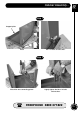
Initial Assembly...
W AXMINSTER W H I T E Initial Assembly... Fitting the guide fence & NVR Switch Fit the guide fence by clipping the rear clamp over the back rail first and dropping the front clamp over the fence rail. (See fig 6) Push down on the lock lever, and ensure the fence clamps up correctly. (See fig 6a). Check the guide fence is set parallel to the blade. Any slight discrepancy can be taken out by loosening the 4 No.
Specification... W AXMINSTER W H I T E Axminster No.
W Identification and Description... AXMINSTER W H I T E Main saw frame The main body of the machine that all the other parts are mounted upon. Upper and lower The two doors that cover the upper and lower saw wheel compartments. cover doors There are interlocks fitted to both doors so that the machine cannot operate if either door is left open. Upper saw wheel The upper saw wheel is mounted on double bearings on an axle that is mounted to a tilting plate.
Illustration and Parts Description...
W Illustration and Parts Description...
Identification and Description... W AXMINSTER W H I T E Saw table insert The saw table insert fits into the round recessed groove in the centre of the table. It not only fills the round void, it also supports the workpiece below the saw in order to minimise ‘breakout’ from the sawcut. The table insert that is supplied is for general work, and woods and white woods to be carried through by the saw blade.
W Illustration and Parts Description...
Identification and Description... W AXMINSTER W H I T E Back rail An aluminium extrusion bolted to the rear of the saw table, that is used as the rear clamp bracket for the guide fence. Tracking control The tracking control wheel, at the rear of the top compartment, is wheel connected to a threaded rod that is engaged in a threaded hole in the base plate of the upper saw wheel axle assembly.
W Identification and Description...
Main Heading...
W Identification and Description...
Identification and Description... W AXMINSTER W H I T E Fig 13a Saw table insert Mitre scale Mitre fence Fig 15 Typ.
W Setting Up the Saw... AXMINSTER W H I T E ! DISCONNECT THE SAW FROM THE MAINS SUPPLY Tensioning and tracking the blade Make sure both top and bottom blade guides are well clear of the blade. Open the front covers fully, giving good access to the top compartment of the saw and good visibility into the bottom compartment (see figs 11 & 12). Check that the blade is sitting approximately in the middle of the wheels.
Setting the Blade Guides... W AXMINSTER W H I T E ! DISCONNECT THE SAW FROM THE MAINS SUPPLY Lower the upper blade guide to approximately 1 1/2"(38mm) above the table. Clamp in place. NOTE: The table has been removed for clarity. Loosen the bolt holding the guide assembly in place (A) and adjust the back to front position so that the leading edges of the side guide bearings are approximately 1.5 mm behind the gullets of the saw blade. Re-tighten the bolt.
W Setting the Fence... AXMINSTER W H I T E To make sure the guide fence is at 90˚line up the guide fence with the edge of the table’s ‘T’ slot. If you find that the fence is out of alignment follow the steps below: • Clamp down the fence by pushing the locking lever down. • Loosen the 4 bolts that secures the fence rail and adjust until the fence is in alignment with the ‘T’ slot, then re-tighten the bolts. • Replace the extension fence. ‘T’ slots Fence Fence rail Locking lever 26 www.axminster.co.
Operating Instructions... W AXMINSTER W H I T E 1. Make sure you have read and fully understood the general instructions and safety precautions that are printed in the preceding pages of this manual. 2. Before connecting the machine to the supply; check the tool for obvious signs of damage, paying particular attention to the plug and the power cable. Rectify or have rectified any damage you discover. Check that the blade you are using is the correct one for the job in hand. Change the blade if necessary.
W Operating Instructions... AXMINSTER W H I T E 13. Do not release the tension on the saw blade when work is complete. The blades and the main saw frame do not respond kindly to constant changes in stress and tension. Only release the tension to change the blade or if the blade is to be removed because the machine is to be ‘mothballed’ for a lengthy time period. (The blade in tension over a long period of non-use will cause the tyres to develop ‘flat’ spots). ! N.B.
Routine Maintenance W AXMINSTER W H I T E Daily •Keep the machine clean. •Check the saw blade for missing teeth and cracks in the fabric. •Spray oil the bare metal surfaces. Weekly •Open the top & bottom wheel covers & clean out all saw dust. Monthly •Open the lower & upper door and check the condition of the tyres & the drive belt. •Clean impacted ‘crud’ from the tyres, apply a little oil to the screw threads of the blade and drive belt tensioners. DO NOT USE OIL near the belt.
W Parts Breakdown Drawing AXMINSTER W H I T E 211530 (AWHBS350N) 30
Parts List...
W Parts List...
Parts Breakdown Drawing W AXMINSTER W H I T E 211531 (AWHBS310N) FREEPHONE 0800 371822 33
W Parts List...
Parts List...
W AXMINSTER W H I T E 36 Cabinet Parts Breakdown & List...
Notes...
W Notes... AXMINSTER W H I T E 38 www.axminster.co.
Notes...
AWHBS350N, AWHBS310N Floor Standing Bandsaw 211530, 211531 W AXMINSTER W H I T E Axminster Reference No: AWHBS350N Axminster Reference No: AWHBS310N Axminster Devon EX13 5PH UK FREEPHONE 0800 371822 www.axminster.co.