Code 501257 AS408 Belt & Disc Sander Axminster Tool Centre, Unit 10 Weycroft Avenue, Axminster, Devon EX13 5PH axminster.co.
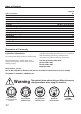
Index of Contents Page No Index of Contents Declaration of Conformity What’s in the Box General Instructions for 230V Machines Specific to Sanding Machines Specification Assembly Assembly Configurations Illustration and Parts Description Sanding Configurations Changing the Sanding Belt Changing the Sanding Disc Maintenance Troubleshooting Wiring Diagram Parts Breakdown Parts List 02 02 03-04-05 06 07-08 08 09-10-11-12-13-14-15-16 17-18 18-19-20 21 22 23 23 24 24 25 26-27 Declaration of Conformity Copied f
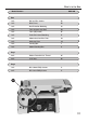
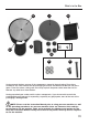
What’s in the Box Model Number: BDS-48Q Box 1 off: Belt and Disc Sander A 1 off: Mitre Fence B 1 off: Dust Extraction Moulding C 1 off: Table Support Steel Rod D 1 off: Table (Adjustable) E 1 off: Pastic Disc Guard Moulding F 1 off: 200mm Cast iron Disc Plate G 1 off: Workstop Plate H 1 off: Sanding Belt I 1 off: 200mm Sanding Disc J 4 off: Rubber Feet with 5/16” Thread K 4 off: 5/16” Nuts K 1 off: M5 x 50mm Phillip Screws L 2 off: M5 x 8mm Phillip Screws L Bag 1
What’s in the Box B C E 04 D
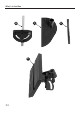
What’s in the Box G J H I F K K L Having opened the box, remove all the components stowed in the packaging. Place these carefully to one side. Remove the top packaging and lift the machine out of the box and place upon a clear flat surface, taking care not to trap or pinch the power cable under the chassis. Remove any other items from the box.
General Instructions for 230V Machines Good Working Practices/Safety The following suggestions will enable you to observe good working practices, keep yourself and fellow workers safe and maintain your tools and equipment in good working order. ! WARNING!! KEEP TOOLS AND EQUIPMENT OUT OF THE REACH OF YOUNG CHILDREN Mains Powered Tools (General) /Disc and Belt Sander Primary Precautions These machines are supplied with a moulded 13 Amp. Plug and 3 core power cable.
Specific to Sanding Machines ! Warning! The sanding disc cannot be declutched from the belt and vice versa, both functions are active when the machine is running. Remember this, and do not leave loose objects of any description, on the machine if it is going to be used. Once the sander is mounted, carry out any setting operations, (mitre, tilt..), and remove all tools used in the setting operations (if any) and place safely out of the way.
Specific to Sanding Machines Check that the belts or discs are undamaged; torn edges can pick up on the workpiece and will cause the medium to tear, often very rapidly with accompanying sharp flapping edges. Always offer the workpiece to the belt/disc so that the motion carries the work against the restraining surface, (i.e. the work stop or the table, (use the left hand side of the disc). Do not press too heavily against the sanding surface, all this will do is slow the sander down.
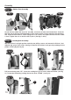
Assembly In order to reduce the footprint of the machine for packaging, several items are dismounted from the machine and need to be re-affixed. Step 1 Drive Belt Assembly Fig 2 Fig 1 a Loosen the two nuts (a) clamping the linisher, using a 13mm spanner. Raise the linisher to the upright position, re-tighten the two nuts (a). Fig 4 Fig 3 b Nut Loosen the phillips screw beneath the linisher, allowing the motor assembly to move freely.
Assembly Step 2 Rubber Feet Assembly Fig 7 Fig 8 K Locate the four rubber feet and 5/16”nuts (K), screw one nut onto the threaded foot. Screw the foot into one of the four pre-drilled holes in each corner of the casting, repeat for the remaining feet. Stand the belt and disc sander up-right on a flat surface and adjust the feet until the sander is level. Tighten the nuts to lock the feet in place.
Assembly Tracking the Belt NOTE1: All directions are given from the view point of the operator standing behind the drive drum end looking down the length of the machine. The tracking control works as follows:- turning the tracking adjuster clockwise will track the belt to the right, anti-clockwise will track the belt to the left. Fig 13 Fig 14 ! DO NOT make large adjustments, and remember the belt may take some time to react to your alteration.
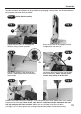
Assembly Step 5 Sanding Disc and Table Assembly Using an abrasive pad, clean the disc drive shaft in readiness for fitting the 200mm cast iron disc (G) (See fig 17). Remove the philips screw from the casting as shown in fig 18 and place safely aside, locate the plastic disc guard moulding (F) and M5 x 50mm phillips screw (L). Slide the guard moulding (F) over the drive shaft and line the pre-drilled hole in the guard with the hole in the casting (See fig 19).
Assembly Slide cast iron disc (G) onto the drive shaft, making sure that the clamping screw lines up with the hole pre-drilled at the top guard moulding (F). Slide a phillips screwdriver down the hole and tighten the screw, clamping the disc to the shaft (See figs 23,24 and 25). Fig 23 Pre-drilled hole F Fig 24 G Fig 25 Slide a phillips screwdriver down the hole and tighten the screw to clamp the disc.
Assembly Locate the table support rod (D) loosen the bolt to the left side of the sanding disc, insert the table support rod (D) and tighten the bolt using a 13mm spanner (See fig 29). Locate the table (E), Offer up the machined hole to the base of the table (E) to the support rod (D) slide it onto the support rod so the edge of the table is just clear of the sanding disc (J), place a level on the table, adjust until the table is level.
Assembly Fig 35 Fig 36 Locate the mitre fence (B) and slide it into the table’s ‘T’ slot (E) (See figs 35 and 36). Place a 90˚ degree square against the mitre fence (B) and check that the table is perpendicular to disc. Your belt and disc sander is now assembled, go round and check that all fixings are secure before operating the machine.
Assembly Configurations Option 1 Table to Linisher Assembly The table (E) can be repositioned to be used when the linisher is raised in the up-right position, see instruction below. Fig 39 Fig 40 H Clamping nuts Loosen the linisher’s clamping nuts, see fig 39, remove the workstop plate (H), see fig 40 (refer to step 4) raise the linisher and clamp in place.
Assembly Configurations Option 2 Workstop Plate Linisher Assembly The workstop plate (H) can be used as a miniature table when the linisher is in the up-right position, see instruction below. Fig 43 Fig 44 H Removing a Remove the workstop plate (H), see fig 43 (refer to step 4) and raise the linisher as before. Remove the dust deflector (a) by removing the two phillips screws and place safely aside (See figs 44 and 45).
Illustration and Parts Description G Fig 47 H Tensioning lever I J Tracking adjuster K E C A F Pointer B NVR On/Off switch Scale D A AS408 Belt and Disc Sander G 200mm Cast Iron Disc Plate B Mitre Fence H Workstop Plate C Dust Extraction Moulding I Sanding Belt D Table Support Steel Rod J 200mm Sanding Disc E Table K Rubber Feet F Plastic Disc Guard Moulding 18 Pointer
Illustration and Parts Description I Fig 48 Linisher H F B Linisher’s back guard A D Motor Motor guard Dust deflector K Spanners Linisher’s back guard dust deflector plate Loosen the two phillips screws and pull the deflector plate down and tighten the screws.
Illustration and Parts Description Fig 49 Configuration 1 Table to Linisher Fig 50 Configuration 2 Workstop Plate used as miniature table 20
Sanding Configurations Fig 54 Fig 51 Surface Sanding Fig 52 Belt Sanding Fig 55 Curve Sanding Fig 53 Bevel Sanding Disc Sanding 21
Changing the Sanding Belt ! DISCONNECT THE SANDER FROM THE MAINS SUPPLY Raise the linisher to the upright position by loosening the two clamping nuts, see figs 1 and 39 and secure in position. refer to (STEP 3 Sanding Belt Assembly), to remove the belt. Inspect the new belt, ensure that there are no tears or rips (especially along the edges), check the direction arrows on the inner surface of the belt and fit accordingly. (The direction of the arrows should point to the drive drum end of the machine).
Changing the Sanding Disc ! DISCONNECT THE SANDER FROM THE MAINS SUPPLY Lift the edge of the disc and, gripping firmly, peel the disc away from the plate; turning the plate as required to free the entire disc. Remove and throw away. If you have been extremely fortunate all the adhesive will have been removed with the disc. As this is rarely the case, be prepared to rub, scrape, pick etc., to remove all the odd patches of adhesive and render the plate CLEAN.
Troubleshooting PROBLEM Motor will not run. POSSIBLE CAUSE REMEDY 1. Defective or broken 1-3. Replace all broken or “ON -OFF” switch. defective parts before using 2. Defective or damaged the sander. switch cord. 3. Defective or damaged switch relay. 4. Burned out motor. 4. Contact Axminster Tool Centre on 0800 371822 and asked to be transferred to 5. Blown fuse. the“Technical Sales” department. Machine slows down while 1. Applying to much pressure 1.
Parts Breakdown 25
Parts List 26
Parts List 27
Please dispose of packaging for the product in a responsible manner. It is suitable for recycling. Help to protect the environment, take the packaging to the local recycling centre and place into the appropriate recycling bin. Only for EU countries Do not dispose of electric tools together with household waste material.