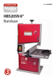
AXMINSTER Hobby SERIES HBS205N 8" Bandsaw Code 508203
Index of Contents Index of Contents Declaration of Conformity What’s Included General Instructions for 230V Machines Specification Assembly Illustration and Parts Description Setting Up the Saw Operating Instructions Changing the Saw Blade Routine Maintenance Parts Breakdown/List Wiring Diagram Bandsaw Blades Notes 02 02 03-04 05-06 06 06-07-08 09-10-11-12-13 14-15-16-17 17-18 18-19 20 21-22-23-24 25 26 27 Declaration of Conformity Copied from CE Certificate Manufactured by Qingdao D&D Electromechanical
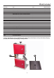
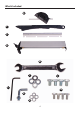
What’s Included Quantity Item Part 1 No 1 No HBS205N 8" Bandsaw Bandsaw Blade 1,400mm Long 6” TPI (Mounted on the saw but not tensioned) Table Fence Rail with Scale Fence Assembly Mitre Fence Push Stick 1 No 1 No 1 No 1 No 1 No A Model Number RBS205 (Code: 508203) B C D E F Bag Containing: G H I J K L M 4 No M6 x 12mm Bolts 4 No M6 Shakeproof Washers 4 No M8x12mm Bolts 4 No M8 Washers 1 No Angled Bolt and Nut 1 No 3mm Hex Key 1 No 10-13mm Spanner 1 No Instruction Manual Having unpacked your s
What’s Included E F C D M J I L G K H 4
General Instructions for 230V Machines not use any solvents or cleaners, as these may cause damage to any plastic parts or to the electrical components. Keep the work area as uncluttered as is practical, this includes personnel as well as material. Good Working Practices/Safety The following suggestions will enable you to observe good working practices, keep yourself and fellow workers safe and maintain your tools and equipment in good working order.
General Instructions for 230V Machines Above all, OBSERVE…. make sure you know what is happening around you and USE YOUR COMMON SENSE. Check that blades are the correct type and size, are undamaged and are kept clean and sharp, this will maintain their operating performance and lessen the loading on the machine.
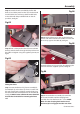
Assembly Step 1 Locate the bandsaw table (B), the four M6 bolts (G) and shake proof washers (H). Slot the blade into the table’s slot and line up the threaded holes in the table with the pre-drilled holes on the tilt quadrant, see fig 02. Fig 04 Fig 02 J I Step 2 Find the fence rail (C), line up the half moon cutouts with the four bolts in the table and insert the fence rail up against the table (B), see fig 05.
Assembly table. Twist the locking lever clockwise to adjust the clamping tension.(Two rotations should be adequate) then press down the lever to lock the fence in position, see figs 07-08. F Fig 07 D Clamping lever Fence rail “T” slot Fig 11 Fig 08 E Table “T” slot Securing the Bandsaw Step 1 Place the bandsaw on a work bench. Mark the position of the holes in the bandsaws base, place the bandsaw to one side and drill the holes.
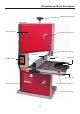
Illustration and Parts Description Blade tensioning knob Upper wheel door Upper door locking screw Upper blade guide and guard Guide fence Blade ON/OFF buttons Mitre fence Fence guide rail Lower wheel door Saw table ‘T’ slot for mitre fence Lower door locking screw 9
Illustration and Parts Description A ON OFF B Mitre fence assembly (A) Index and pointer (B) Table levelling stop bolt ON/OFF NVR switch assembly A B B A Blade guide adjusting knob (A) Blade guide clamp (B) Tracking control knob (A) Tracking control butterfly lock (B) A C B Blade tensioning knob Tilt quadrant (A), Tilt scale (B) Tilt scale pointer and adjusting screw (C) 10
Illustration and Parts Description Main saw frame Tracking control knob and lock Upper blade guide adjusting knob Upper blade guide clamp MItre fence Table insert Push stick Power cable Saw table Tilt mechanism Tilt mechanism clamp Dust extraction outlet Motor assembly Motor air vents 11
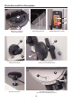
Illustration and Parts Description A B A B Lower blade guide assembly (A) Blade guide pin and clamping grub screw (B) B Upper blade guide assembly (A) Rear thrust bearing and clamping grub screw (B) A A Lower blade guide guard (A) Rear thrust bearing and clamping grub screw (B) Upper guide assembly fore and aft clamping grub screw (A) Decrease tension A B Increase tension Blade tensioning spring (A), under tension Blade tensioning spring (B) with no tension applied 12 Twist the locking lever
Illustration and Parts Description Upper saw wheel Upper wheel mounting Blade guide assembly Fence clamping lever Saw table slot Lower saw wheel Saw wheel brush Dust extraction outlet 13
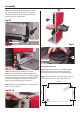
Setting Up the Saw Fig 12 DISCONNECT THE SAW FROM THE MAINS SUPPLY! Tensioning and tracking the blade Blade Make sure both top and bottom blade guides are well clear of the blade. Tyre Open the front covers fully, giving good access to the top compartment of the saw and good visibility into the bottom compartment. (see page 13). For tracking the blade first adjust all bearing guides so that there well clear of the blade.
Setting Up the Saw Checking the table is square If the preset table stop has been fitted, proceed as follows:Loosen the butterfly nut clamping the tilt mechanism, see fig 15, and turn the table hard against its stop. This is a bolt with a lock nut screwed into the underside of the table, see fig 16, that acts as a stop when it strikes the machine frame. Tighten the butterfly nut. Check that the blade is perpendicular to the table. If it is not, try resetting the table.
Setting Up the Saw Fig 24-25 DISCONNECT THE SAW FROM THE MAINS SUPPLY! Setting the Blade Guides Lower the upper blade guide to approximately 1 1/2”(38mm) above the table by loosening the blade guide height clamp and turning the adjusting knob. Clamp in place, see figs 21-22. Loosen the grub screw (A) holding the guide assembly in place, see fig 23. Adjust the fore or aft position so that the leading edges of the side guide pins are approximately 2mm behind the gullets of the saw blade.
Setting Up the Saw Fig 27 D Close the upper and lower doors, re-connect the power, switch the saw on, allow to run for several minutes, check that the blade is still tracking correctly, there is no excessive vibration, etc. Switch off and wait until the saw comes to a complete stop. The saw is ready to be used. Operating Instructions Guide pin 1. Make sure you have read and fully understood the general instructions and safety precautions that are printed in the preceding pages of this manual.
Operating Instructions Do not try to cut too quickly; the correct cutting speed, if one could be so precise, would never see the blade pushed back against the thrust bearing The saw would cut and clear the saw line at the rate the work piece was fed into it. If you notice that you require more and more pressure to effect the cut, and the blade is in continual contact with the thrust bearing, the chances are the blade is becoming blunt. Check and change if necessary.
Changing the Saw Blade mounting assembly could likewise be lightly oiled. If you are fitting a new blade it will have been supplied to you “folded”, bound together in this configuration with tape or tie wrap. Also check the blade did not “unfold” inside out. i.e. looking at the right side front of the loop, the teeth should be on the front of the blade, and pointing down. If you can’t arrive at this view, turn the blade inside out from its current position and look again. lower blade guides, see fig 31.
Routine Maintenance Daily Monthly • Keep the machine clean. • Open the lower and upper doors and check the condition of the tyres & the drive belt, see fig 34. • Check the saw blade for missing teeth and cracks, see fig 34. • Spray oil the bare metal surfaces. Weekly • Open the top & bottom wheel covers and clean out all saw dust. Clean out impacted ‘crud’ & saw dust • Clean impacted ‘crud’ from the tyres, apply a little oil to the screw threads of the blade and drive belt tensioners.
Parts Breakdown/List 21
Parts Breakdown/List ITEM PART NO. NAME Q’ty 1 DJ200020200 Rip fence assembly 1 2 DJ200020103A Support 3 3 31503009A Locking knob 1 4 DJ200020101D Working table 3 5 DJ25002005 Table insert 1 6 DJ200020112 Rip fence carrier extrusion 5 7 GB/T14 M6×16 Screw 1 8 31502015 Knob 1 9 GB/T14 M6×16 Screw 2 10 DJ25002006A Guide piece 1 11 DJ250A02003 Table trunnion upper 6 12 GB/T862.
Parts Breakdown/List ITEM PART NO. NAME Q’ty 35 DJ200030801 Saw blade 1 36 GB5783-86 M6×12 Hex Bolt 8 37 31503030 Tongue 2 38 31503033 Housing with nut 2 39 DJ200010301G Door lower 1 40 31503020 Washer 2 41 31503032 Tongue housing 2 42 31503031 Slotted insert 2 43 GB97.1-85 4 Washer 4 44 GB818-85 M4×6 Cross recessed pan head screw 7 45 DJ200010201H Door upper 1 46 GB894.
Parts Breakdown/List ITEM PART NO. NAME Q’ty 69 DJ200020108 Plank 1 70 DJ200020102 Locking handle 1 71 DJ200030406 Locking knob 1 72 DJ250A05005 Power cord and plug 1 73 DJ200030405 Setting knob 1 74 DJ200030407 Spring 1 75 DJ200030408 Dishing cover 1 76 GB97.
Wiring Diagram 25
Bandsaw Blades Standard Axcaliber Bandsaw Blades 1,400mm(55”) x 0.
Notes 27
The Axminster guarantee is available on Hobby, Trade, Industrial, Engineer, Air Tool & Axcnc Technology Series machines It’s probably the most comprehensive FREE guarantee ever- buy with confidence from Axminster! So sure are we of the quality, we cover all parts and labour free of charge for three years! • Look for the icon and put your trust in Axminster • No registration necessary - just keep your proof of purchase • Optional Service Plan for Industrial Series machinery Great value & easy-to-use, perfec