Code: 501242 TS-200 200mm Basic Table Saw 501248 Leg Stand Hole assembly instructions including leg stand extension table and sliding table kits 501254 Sliding Table Kit 700058 R/H Extension Table Product Code Kits 717218: TS-200 Table Saw 501242: TS-200 Basic Saw 501248: TS-200 Leg Stand 700058: TS-200 R/H Extension Table Kit 501254: TS-200 Sliding Table Kit Axminster Tool Centre, Unit 10 Weycroft Avenue, Axminster, Devon EX13 5PH 717218 Table Saw axminster.co.
Index of Contents Page No.
Parts Index Model Number: Quantity HM-TS200 Kit Order No’s Description 1 off Basic Table Saw (with Saw Blade & Riving Knife fitted) A 501242-717218 2 off Sliding Carriage Supporting Arms B 501254 1 off Push Stick B1 501242-717218 1 off Mitre Fence Steel Bar B2 501242-717218 1 off Saw Guard Steel Mesh B3 501242-717218 1 off Work Clamp Assembly C 501242-717218 1 off Sliding Carriage Table D 501254 1 off Mitre Fence E 501242-717218 2 off Operating Wheel Handles F 501242-717
Parts Index Kit Order No’s 32 off M8 x 12 Coach Bolts with Nuts 4 off M8 x 11 Bolts with Large Washer & Nut T 1 off Saw Guard with M6 x 25 Coach Bolt & Nut U 501248-717218 1 off Carriage Arm V 1 off Angle Fence W 501254-717218 2 off Extension Table Supporting Arms X 700058-717218 1 off Extension Table Y 700058-717218 1 off Fence Z 501242-717218 2 off Hose 50mm & 30mm Z1 501242-717218 2 off Jubilee Clips 50mm & 30mm Z2 950650,718641 6 off M6 x 25 Phillip Head Screw 6 off M
Parts Index C D Box L E I J G M O F H K N 05
Parts Index P Q R S T U W1 V W W1 X 06
Parts Index Z1 Z Y Z1 Z2 Z3 General Instructions for 230V Machines Good Working Practices/Safety The following suggestions will enable you to observe good working practices, keep yourself and fellow workers safe and maintain your tools and equipment in good working order. ! WARNING!! KEEP TOOLS AND EQUIPMENT OUT OF THE REACH OF YOUNG CHILDREN Mains Powered Tools Primary Precautions These machines are supplied with a moulded 13 Amp. Plug and 3 core power cable.
General Instructions for 230V Machines Fuse as required. If extension leads are to be used, carry out the same safety checks on them, and ensure that they are correctly rated to safely supply the current that is required for your machine. Work Place/Environment The machine is not designed for sub-aqua operation, do not use when or where it is liable to get wet. If the machine is to be used outside and it starts to rain (unusual though this would be in U.K.), stop work and move it inside.
General Instructions for 230V Machines DO NOT use this machine within the designated safety areas of flammable liquid stores or in areas where there may be volatile gases. There are very expensive, very specialised machines for working in these areas, THIS IS NOT ONE OF THEM. Check that cutters, drills, blades etc., are the correct type and size, are undamaged and are kept clean and sharp, this will maintain their operating performance and lessen the loading on the machine.
Specific Instructions/Precautions for the Saw Table ALWAYS disconnect the machine if you are leaving it unattended. NEVER leave the vicinity of the machine unless the blade has come to a complete stop. DO NOT attempt to carry out any maintenance, corrective work, setting up etc., unless the machine is disconnected from the mains supply. If any tools have been used during setting up procedures, make sure they are removed from the machine and stowed safely away.
Assembly Instructions Initial Assembly Please take some time to read the section entitled “Identification and Parts Description” to identify the various parts of your machine so that you are familiar with the terminology we will use to enable you to set up and operate your table saw safely and correctly. Assembling the stand Locate and identify the 4 legs (P), the short struts (R) and the long struts (Q) for the stand, and the packet containing 32 M8 x 10mm coach bolts, washers and nuts.(T).
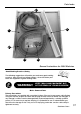
Assembly Instructions Attaching the Saw Guard Steel Mesh Locate the Saw Guard Steel Mesh (B3), turn the Saw Bench (A) upside down and remove the four phillips screws & washers to each corner of the frame. Lay the Saw Guard Steel Mesh on top of the frame and replace the phillip screws & washers to secure it in position. (See fig 4 & 4a). Fig 4 A Fig 4a B3 Attaching the Saw Bench to the Stand Phillips screw & washer With assistance, place the Saw Bench (A) onto the stand.
Assembly Instructions Assembling the Sliding Carriage Table Place an M6 x 16mm hex bolt in each of the four clearance holes on both support arms (B), and loosely put an M6 nut and washer on the bottom of each. (See fig 8). Slide the extruded carriage arm (V) onto the four M6 x 16mm bolts. (See fig 9).
Assembly Instructions Angle Fence Assembly Put to hand the work clamp block (O), and slide it onto the T-slot on the angle fence (W). Locate the connecting block (O) and slide it onto the angle fence as before. (See fig 14). Slide the T-bolt on the base of the connecting block (O) into the T-slot on the sliding carriage table (D), see fig 16. Locate the plastic block (W1) and using the two phillips screws secure it to the end of the angle fence (W) (See fig 15).
Assembly Instructions Angle Fence Assembly Fig 21 Fig 20 To set the angle fence (W) to angles between 45˚ and 90˚ loosen the three lift and shift handles on the connecting & work clamp blocks (O) and the fence to the required angle on the scale on the sliding carriage table (D). (See figs 22). Tighten the three lift & shift handles to lock the angle fence in position. Note: The fence can also be used at the rear of the sliding carriage table if you prefer to push the timber against the fence.
Assembly Instructions J Fig 26 Fig 27 a F Tilt operating wheel handle Operating Wheel Handles Assembly Locate the two operating wheel handles (F) and, using the supplied 3mm allen key (J), secure one to the tilt mechanism shaft to the front of the saw by undoing the grub screw on the operating wheel handle (F) and sliding it onto the shaft, making sure the grub screw is in line with machined slot (a), in the shaft. Retighten the grub screw.
Assembly Instructions Locate the two extension table support arms (X). Remove the plastic cover to the left hand side of the support arm with the scale. (See fig 32). Slot the extension table support arm (X) onto the M6 nuts so that nut sits in the T -slot. (See fig 33) Push the support arm so it is flush with the end of main table and lightly secure the extension support arm to the main table using a phillips screwdriver. Replace the plastic cover you removed earlier. (See figs 34 & 35).
Assembly Instructions Extension Table Assembly Part 2 Remove the plastic covers from the ends of the two extension table support arms (X), (see fig 38). Offer up the M6 nuts to the support arms T-slots and slide the extension table (Y) into the extension support arms (X).
Assembly Instructions Fence Assembly Lower the fence assemby so the clamp assembly (N) slots over the extention table support arm (X), clamp the fence assembly in position by turning the knob clockwise. (See figs 44 & 45). Note: Check that the fence is parallel to the saw blade by sliding it up against it. If the fence is out of alignment loosen the steel square clamp bolt beneath the clamp assembly (N) and adjust until correct, re-tighten the bolt. (See figs 43 & 46).
Assembly Instructions Dust Extraction Assembly (717218 Only) Remove the nuts, bolts & washers from the 30mm hose support bracket (H), line up the pre-drilled holes to the underside of the rear extention support arm (X) & secure using the nuts,bolts & washers you removed earlier. (See figs 50 & 51). Locate the dust extraction moulding support bracket (I) & slot the bracket’s ring over the end of the 50mm inlet on the dust extraction moulding (L).
Illustration & Parts Description G W C E U D M Z W1 Y O N A V F F NVR On/Off switch shroud X R P T S Q A Saw Bench M Flip Over Stop B1 Push Stick O Work Clamp/Connecting Blocks C Work Clamp Assembly P Leg ‘A’ Frames D Sliding Carriage Table Q Long Struts E Mitre Fence R Short Struts F Operating Wheel Handles S Rubber Feet G Mitre Fence Clamping Knob T M8 x 12 Coach Bolts with Nuts H 30mm Hose Support Bracket U Saw Guard I Dust Extraction Support Bracket V Carriage Arm L 100mm
Illustration & Parts Description Z D X Y V I B1 Z1 A Z1 L 22 H X Extension Table Support Arms Z Fence Y Extension Table Z1 Hoses 50mm & 30mm
Setup & Adjustments Adjusting the Riving Knife Raise the saw blade to its highest point and remove the saw blade guard. Remove the four hex screws and place carefully aside, remove the table insert. Using the spanner provided loosen the riving knife and adjust until the tip of the riving knife is 3mm away from the saw blade & re-tighten. (See fig 54). NOTE: Check that the riving knife is parallel to the saw blade by placing the fence up against them. (See fig 55).
Setup & Adjustments Adjusting the Fence to the Blade The fence (Z) can be repositioned to face the opposite direction for guiding thin timber pieces through. Loosen the square clamp bolt beneath the clamp assembly (N), See fig 57, turn the fence (Z) around so the large surface of the fence is pointing away from the blade, re-attach the fence clamp assembly (N). The two illustrations below, figs 60 & 61, shows the fence in both positions.
Operating Instructions ! NOTE: Before using your table saw, go round and make sure everything is secure, fastened down, that all tool, are cleared away from the work area. ! CHECK the blade for sharpness, missing teeth, resin buildup, etc., clean if necessary. Check the blade is securely clamped in place. (i.e. not loose). ! CONNECT THE SAW TO THE MAINS SUPPLY Give the machine a 'quick' burst check ( i.e. quick ON-OFF) to ensure everything is O.K.
Operating Instructions The Mitre Fence The mitre fence can be mounted on either side of the saw blade in the two ‘T’ slots, pre machined into the saw table. (See fig 26). The mitre fence can be angled from 90˚ to 45˚ degrees. (See fig 66).
Changing the Saw Blade Fig 69 Sawplate washer Fig 70 Remove the saw blade Tighten up the saw bolt, check the riving knife is aligned with the saw blade, and correctly positioned. Replace the table insert and secure with the 4 hex screws. Replace the saw blade guard. When everything is satisfactory, turn the saw blade once by hand to check it doesn't foul anywhere. Reconnect the machine to the mains supply. Give the machine a 'quick' burst check ( i.e. quick ON-OFF) to ensure everything is O.K.
Parts Breakdown for TS-200 Table Saw 28
Parts Breakdown for TS-200 Table Saw 29
Parts List for TS-200 Table Saw 30
Parts LIst & Breakdown for the Sliding Carriage 31
Please dispose of packaging for the product in a responsible manner. It is suitable for recycling. Help to protect the environment, take the packaging to the local recycling centre and place into the appropriate recycling bin. Only for EU countries Do not dispose of electric tools together with household waste material.