
Specifications


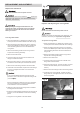


Fitting the rip fence and align the rail
.
1.Move the blade tilt to 0˚ (blade 90˚ to table), and raise
the main blade as the way up.
2.Fit the profile of the rip fence carrier into the opposite
profile on the rip fence rail.
.
3.Slide the rip fence touch the main blade.
panel
4. Tap the right end of rip fence rail to ensure the '0'
scale on rail aligned with the red line on lens of rip
fence carrier.
2. panel panel
.
3.
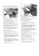
2 Place the cross-cut table support (A) onto the swing
arm assembly, and hand tighten the lock nuts. The
support needs further adjustment.
Install the Sliding panel assembly
1 Place 2 sets of star-type screws (include 8mm
washer, insert, screw guide) into the lower slot of
sliding carrier ( see above 14).
Put the sliding assembly onto the sliding
supports, and lay two star-type screws as fig 15 show.
Install the swing arm assembly
1 Place 4 M8x30 hex head screws to mount the swing
arm assembly to the saw base unit, and keep the arm
on horizontal level.
Tighten two star-type screws.
4. Install the support leg to the sliding carrier.
A
A
B
C
10
Fig 10
Fig 11
Fig 12
Fig 13
Fig 14